
Page 71 - Geothermal Energy Systems Exploration, Development, and Utilization
P. 71
2.3 Relevance of the Stress Field for EGS 47
The Mohr–Coulomb failure criterion
t in MPa Fluid pressure: 0.00
R = 0.044
Additional fluid pressure
UCS = moderate t in MPa
t = c +µ*s n
µ= tanf
60
f s npf = s n − Pf
c 2q
s 3 s 1 s 3 s n s 3 s in MPa
Pf
s npf s 3 s n s 2 s 1 s in MPa
s 1 s 1 s 1
q
A B C
q = 0° 0°> q < 22.5° q > 22.5°
(a) (b)
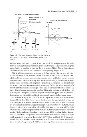
Figure 2.3 The Mohr–Coulomb failure criterion (see text).
(Please find a color version of this figure on the color
plates.)
stresses acting on fracture planes. Which plane will fail is dependent on the angle
between failure plane and maximum principal stress axis s1. By understanding the
stress field it is possible to estimate the orientation of likely failure planes in the
current stress field based on Anderson’s faulting theory (Figure 2.2a).
Additional fluid pressure as happened with fluid injection during reservoir stim-
ulation has a significant effect on failure. As shown in the illustration (Figure 2.3b),
additional fluid pressure decreases the normal stress and failure occurs as soon
as critical shear conditions acting on a plane are reached (as defined by the green
critical shear envelope). Existing fault planes have no cohesion (as illustrated in
the above case), so it is easier to reactivate existing faults even when not optimally
orientated to the maximum principal stress axis. Reactivation of faults is commonly
shear failure because even under very low differential stresses tensile failure (the
blue dot) and also hybrid shear failure (pink dot) would happen after shear failure.
Only under very high additional fluid pressures all kinds of failure could occur.
An understanding of the state of stress is important for reservoir evaluation in
terms of fluid flow. The stress state of faults affects the transmissivity within an
often complex fault pattern. Transmissivity, which is the extent to which fractures
are hydraulically conductive, depends strongly on their aperture (Cook, 1992), which
in turn is primarily, yet not solely, affected by the fracture orientation within the in
situ stress field. Preexisting faults and fractures that are critically stressed for either
tensile (Gudmundsson, Fjeldskaar, and Brenner, 2002) or shear failure Barton,
Zoback, and Moos, 1995) within the in situ stress field are most likely to be open
and hydraulically conductive (Ferrill et al., 1999; Talbot and Sirat, 2001). Generally,
tensile failure is unlikely to be the dominant fracture reactivation mechanism
below a depth of approximately 2000 m, as the high lithostatic overburden causes