
Page 339 - Global Tectonics
P. 339
322 CHAPTER 10
In the experiments of Robl & Stüwe (2005a) indenter is similar to that with an indenter
Asia is modeled as a viscous sheet consisting angle of α = 45°. These results indicate
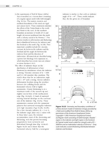
of a regular square mesh with 3200 triangles that, for the given set of boundary
(Fig. 10.23a). The eastern, western, and
northern boundaries of the mesh are rigid
and cannot move. These constraints simulate (a)
the effects of the Tarim Basin to the north 0.9 W N E
and Pamir to the west. At the southern S
boundary an indenter of width (D/2) and 0.8
length (ω) moves northward into the mesh 0.7
−1
with a velocity scaled to be 50 mm a . This
0.6 Foreland
motion results in deformation and thickening
that is distributed between the indenter and 2D 0.5
the foreland to the north (Fig. 10.23b). Two
0.4
important variables include the viscosity α Indenter
contrast (η) between the indenter and the 0.3
foreland and the angle (α) between the 0.2 w
indenter front and the direction of y
0.1
indentation. All materials are described using x 1
2 D
a power law rheology with exponent (n),
1 1
which describes how strain rates are related 2 D 2 D
to stress (Section 2.10.3). 2D
The effect of indenter shape on the (b)
distribution of deformation is best 3
illustrated in simulations where the indenter 10 km km Crustal thickness n = 3
is strong. Viscosity contrasts of η = 1000 8 40 50 60 70 80 t = 30 Myr
and η = 100 simulate this condition. The α = 0.4 D
η = 3
results show that for an indentation angle
of α = 45° and a strong, viscous indenter, 6
deformation localizes along the interface
between the colliding blocks and the
horizontal velocity field is highly 4 40
asymmetric. Crustal thickening is at a 45
maximum north of the western tip and
slightly less in front of the northeastern 2 50 45 50
edge (Fig. 10.24a,b). A band of eastward-
moving material develops on the northeast 35 35
side of the indenter (Fig. 10.25a). These 2 4 6 8 x 10 km
3
asymmetries contrast with the symmetric
patterns that surround rectangular indenters
Figure 10.23 Geometry and boundary conditions of
with high viscosities (Figs 10.23b, 10.25b).
a finite element model of indention (image provided by
For a low viscosity indenter (η = 2 or 3),
J. Robl and modified from Robl & Stüwe, 2005a, by
the indenter angle plays only a minor role. permission of the American Geophysical Union.
In these latter cases, the indenter Copyright © 2005 American Geophysical Union).
accommodates most of the shortening and (a) Regular mesh consisting of 3200 triangles. Shaded
thickening, with the pattern becoming region is the indenter and light region is the foreland.
progressively more symmetric and (b) Typical model result scaled for a length scale of D =
delocalized through time (Fig. 10.24c,d). 5000 km and an indentation velocity of 50 mm a . Gray
−1
Figure 10.25c and d show that the scale indicates crustal thickening distributed between
horizontal velocity field for a rectangular indenter and foreland.