
Page 167 - HVAC Pump Handbook
P. 167
Rishel_CH06.qxd 20/4/06 6:06 PM Page 164
HVAC Pump Performance
164 HVAC Pumps and Their Performance
bottom inlet, as shown in Fig. 6.17b; a side inlet can be corrected by
placing an antivortexing plate above the inlet (Fig. 6.17c). On shallow
cooling tower sumps, if vortexing persists, it may be necessary to in-
stall a slotted vortex breaking tube, as shown in Fig. 6.18d. As an al-
ternative, an elbow can be installed on the suction connection of a
side inlet and pointed downward, as shown in Fig. 6.17e. If vortexing
still occurs, a square plate can be installed on the suction of the elbow.
Vortex-breaking devices must be designed to avoid substantial addi-
tional friction losses. Normally, the friction loss of an entrance from a
2
tank is equal to about 0.5 V /2g, where V is the velocity of the
water in the entering pipe. The vortex-breaking device should not
increase this entrance loss if possible.
A simple method to determine if vortexing is occurring is to place
mats or rafts on the water surface above the inlet from the tank. This
prevents the vortex from forming and can be done without draining
the tank.
Vortexing should not occur in HVAC tanks and sumps. The precau-
tions are so simple that the design of these tanks and sumps should
always accommodate them.
6.5.3 Submergence of pumps in wet pits or
open tanks
Pumps installed in a tank, such as vertical turbine pumps, have a
specific submergence requirement. The submergence, or distance
above the inlet bell of such a pump, must be great enough to ensure
that the friction loss of the water passing through the bell and enter-
ing the pump is made up by the static height of the water over the
suction bell. This height is determined by whether the suction of the
pump is or is not equipped with a suction strainer. Most manufactur-
ers of axial-flow pumps have adequate data on submergence and
clearance from the bottom of the tank for the water system designer;
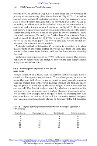
their recommendations should always be followed. Table 6.1 describes
TABLE 6.1 Typical Submergences for Vertical Turbine Pumps (for Operation at
1750 rev/min)
Bowl size, in Submergence, in Bowl size, in Submergence, in
04 07 13 23
06 11 14 30
08 12 15 32
10 16 16 36
11 20 18 36
12 24 20 42
Downloaded from Digital Engineering Library @ McGraw-Hill (www.digitalengineeringlibrary.com)
Copyright © 2006 The McGraw-Hill Companies. All rights reserved.
Any use is subject to the Terms of Use as given at the website.