Page 62 - HVAC Pump Handbook
P. 62

Rishel_CH03.qxd  20/4/06  5:35 PM  Page 59


                                           Piping System Friction
                                                               Piping System Friction  59

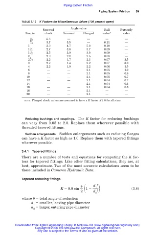
                    TABLE 3.12  K Factors for Miscellaneous Valves (100 percent open)

                                               Angle valve
                                Screwed                           Ball     Butterfly
                      Size, in   check     Screwed    Flanged    valve*     valve
                         1
                         ⁄ 2      5.6        —          —         —          —
                         3
                         ⁄ 4      3.7        5.5        —         0.11       —
                        1         3.0        4.7        5.0       0.10       —
                         1
                        1 ⁄ 4     2.7        3.8        3.7       0.09       —
                         1
                        1 ⁄ 2     2.5        3.0        3.0       0.09       —
                        2         2.3        2.2        2.5       0.08       —
                         1
                        2 ⁄ 2     2.2        1.7        2.3       0.07       3.5
                        3         2.2        1.4        2.2       0.07       3.0
                        4         2.2        1.0        2.2       0.06       1.5
                        6         —          —          2.1       0.05       1.0
                        8         —          —          2.1       0.05       0.8
                       10         —          —          2.1       0.05       0.7
                       12         —          —          2.1       0.04       0.7
                       14         —          —          2.1       0.04       0.6
                       16         —          —          2.1       0.04       0.6
                       18         —          —          2.1       —          —
                       20         —          —          2.1       —          —
                      NOTE: Flanged check valves are assumed to have a K factor of 2.0 for all sizes.


                      Reducing bushings and couplings. The K factor for reducing bushings
                    can vary from 0.05 to 2.0. Replace them wherever possible with
                    threaded tapered fittings.
                      Sudden enlargements. Sudden enlargements such as reducing flanges
                    can have a K factor as high as 1.0. Replace them with tapered fittings
                    wherever possible.

                    3.4.1 Tapered fittings
                    There are a number of tests and equations for computing the K fac-
                    tors for tapered fittings. Like other fitting calculations, they are, at
                    best, approximate. Two of the most accurate calculations seem to be
                    those included in Cameron Hydraulic Data.

                    Tapered reducing fittings


                                                              2
                                                            d 1 2
                                          K   0.8 sin    1                       (3.8)
                                                     2      d
                                                             2
                    where    total angle of reduction
                         d   smaller, leaving pipe diameter
                           1
                         d   larger, entering pipe diameter
                           2

                 Downloaded from Digital Engineering Library @ McGraw-Hill (www.digitalengineeringlibrary.com)
                            Copyright © 2006 The McGraw-Hill Companies. All rights reserved.
                             Any use is subject to the Terms of Use as given at the website.
   57   58   59   60   61   62   63   64   65   66   67