Page 64 - HVAC Pump Handbook
P. 64

Rishel_CH03.qxd  20/4/06  5:35 PM  Page 61


                                           Piping System Friction
                                                               Piping System Friction  61

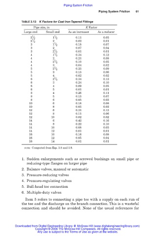
                    TABLE 3.13  K Factors for Cast Iron Tapered Fittings
                           Pipe size, in                K Factor
                     Large end    Small end   As an increaser  As a reducer
                          1           1
                         2 ⁄ 2       1 ⁄ 2        0.11           0.05
                          1
                         2 ⁄ 2       2 1          0.02           0.01
                         3           1 ⁄ 2        0.18           0.07
                         3           2            0.07           0.04
                                      1
                         3           2 ⁄ 2        0.01           0.01
                                      1
                         4           1 ⁄ 2        0.34           0.12
                         4           2            0.21           0.08
                                      1
                         4           2 ⁄ 2        0.10           0.05
                         4           3            0.04           0.02
                                      1
                         5           2 ⁄ 2        0.23           0.09
                         5           3            0.13           0.06
                         5           4            0.02           0.02
                                      1
                         6           2 ⁄ 2        0.34           0.13
                         6           3            0.24           0.10
                         6           4            0.09           0.05
                         6           5            0.01           0.01
                         8           4            0.26           0.11
                         8           5            0.13           0.07
                         8           6            0.05           0.03
                        10           6            0.18           0.08
                        10           8            0.03           0.02
                        12           6            0.31           0.13
                        12           8            0.11           0.06
                        12           10           0.02           0.02
                        14           6            0.42           0.16
                        14           8            0.22           0.10
                        14           10           0.08           0.05
                        14           12           0.01           0.01
                        16           10           0.16           0.08
                        16           12           0.05           0.04
                        16           14           0.01           0.01
                      NOTE: Computed from Eqs. 3.8 and 3.9.


                    1. Sudden enlargements such as screwed bushings on small pipe or
                       reducing-type flanges on larger pipe
                    2. Balance valves, manual or automatic
                    3. Pressure-reducing valves
                    4. Pressure-regulating valves
                    5. Bull-head tee connection
                    6. Multiple-duty valves
                      Item 5 refers to connecting a pipe tee with a supply on each run of
                    the tee and the discharge on the branch connection. This is a wasteful
                    connection and should be avoided. None of the usual references for


                 Downloaded from Digital Engineering Library @ McGraw-Hill (www.digitalengineeringlibrary.com)
                            Copyright © 2006 The McGraw-Hill Companies. All rights reserved.
                             Any use is subject to the Terms of Use as given at the website.
   59   60   61   62   63   64   65   66   67   68   69