
Page 63 - HVAC Pump Handbook
P. 63
Rishel_CH03.qxd 20/4/06 5:35 PM Page 60
Piping System Friction
60 The Basic Tools
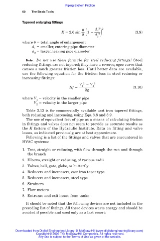
Tapered enlarging fittings
2
d 1 2 2
K 2.6 sin 1 (3.9)
2 d
2
where total angle of enlargement
d smaller, entering pipe diameter
1
d larger, leaving pipe diameter
2
Note. Do not use these formula for steel reducing fittings! Steel
reducing fittings are not tapered; they have a reverse, ogee curve that
causes a much greater friction loss. Until better data are available,
use the following equation for the friction loss in steel reducing or
increasing fittings:
V 2 V 2
1
2
Hf (3.10)
2g
where V velocity in the smaller pipe
1
V velocity in the larger pipe
2
Table 3.13 is for commercially available cast iron tapered fittings,
both reducing and increasing, using Eqs. 3.8 and 3.9.
The use of equivalent feet of pipe as a means of calculating friction
in fittings and valves does not seem to provide as accurate results as
the K factors of the Hydraulic Institute. Data on fitting and valve
losses, as indicated previously, are at best approximate.
Following is a list of the fittings and valves that are encountered in
HVAC systems:
1. Tees, straight or reducing, with flow through the run and through
the branch
2. Elbows, straight or reducing, of various radii
3. Valves, ball, gate, globe, or butterfly
4. Reducers and increasers, cast iron taper type
5. Reducers and increasers, steel type
6. Strainers
7. Flow meters
8. Entrance and exit losses from tanks
It should be noted that the following devices are not included in the
preceding list of fittings. All these devices waste energy and should be
avoided if possible and used only as a last resort:
Downloaded from Digital Engineering Library @ McGraw-Hill (www.digitalengineeringlibrary.com)
Copyright © 2006 The McGraw-Hill Companies. All rights reserved.
Any use is subject to the Terms of Use as given at the website.