
Page 64 - Hacking Roomba
P. 64
Chapter 3 — Building a Roomba Serial Interface Tether 45
RS-232 transceiver s sub-circuit
VCC VCC
IC1 1µF
C5 1
C1+ 16 VCC
V+ 2 C1
1µF 3
C1- IC1P
V– 6
4 1µF GND
C6 C2+ 15
5 C7
1µF C2-
mini-din 8pin
8 11 T1IN T1OUT 14
7 GND 10 T2IN T2OUT 7 GND GND X1
6 DD 12 R1OUT R1IN 13 1
5 TXD 9 R2OUT R2IN 8 2 6
4 3 7
3 RXD MAX232 4 8
2 5 9
1
X2 VCC DB-9 female cable
+16VDC
IN OUT
C3 GND C2 LED1 green
IC2
1µF 78L05 1µF
220' R1
GND GND
voltage regulator LED
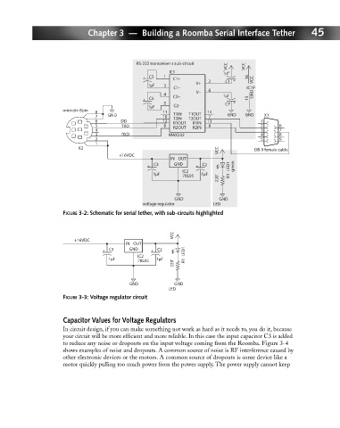
FIGURE 3-2: Schematic for serial tether, with sub-circuits highlighted
VCC
+16VDC
IN OUT
C3 GND C2 LED1
IC2
1µF 78L05 1µF
220' R1
GND GND
LED
FIGURE 3-3: Voltage regulator circuit
Capacitor Values for Voltage Regulators
In circuit design, if you can make something not work as hard as it needs to, you do it, because
your circuit will be more efficient and more reliable. In this case the input capacitor C3 is added
to reduce any noise or dropouts on the input voltage coming from the Roomba. Figure 3-4
shows examples of noise and dropouts. A common source of noise is RF interference caused by
other electronic devices or the motors. A common source of dropouts is some device like a
motor quickly pulling too much power from the power supply. The power supply cannot keep