
Page 68 - Hacking Roomba
P. 68
Chapter 3 — Building a Roomba Serial Interface Tether 49
Getting Ready
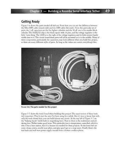
Figure 3-6 shows the parts needed all laid out. From here you can see the difference between
the Mini DIN cable (round ends) and the DB9 cable (flat ends). From this particular set of
parts, the 1 µF capacitors are the five lighter cylinders and the 10 µF one is the smaller black
cylinder. The MAX232 chip is the black square with 16 pins, and the voltage regulator is the
little 3-pin thing. The LED is to the right of the voltage regulator, and its little resistor barely
visible next to it. The circuit board these parts will all be mounted on is in the middle. Many of
these components, particularly the capacitors, may look different when you build this project,
as there are many different styles of parts. As long as the values are correct, everything’s fine.
FIGURE 3-6: The parts needed for this project
Figure 3-7 shows the tools I used when building this project. The exact version of these tools
isn’t important. They’re just the ones I’ve been using for a while. But it’s nice to know that with
only the tools shown here, you can build almost any circuit. At the top left of Figure 3-7 are
the “helping hands” (with built-in magnifying lens). Next to them is the multimeter and sol-
dering iron. Weller makes good irons. This particular iron is temperature controlled, which is
why it has a base station, but it’s a feature not needed for these projects. At the lower left are
some cheap cutters, needle nose pliers, and glue gun I got at a swap meet. Finally there’s the
test leads and wall wart power supply rescued from a broken cordless phone.