
Page 71 - Hacking Roomba
P. 71
52 Part I — Interfacing
Also, create test points using snipped leads to check voltages. Sometimes the jumpers can dou-
ble as test points. Test points for Vpwr, Vcc, and GND should be created.
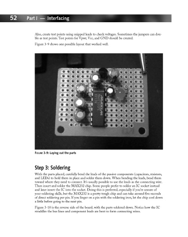
Figure 3-9 shows one possible layout that worked well.
FIGURE 3-9: Laying out the parts
Step 3: Soldering
With the parts placed, carefully bend the leads of the passive components (capacitors, resistors,
and LEDs) to hold them in place and solder them down. When bending the leads, bend them
toward where they need to connect. It’s usually possible to use the leads as the connecting wire.
Then insert and solder the MAX232 chip. Some people prefer to solder an IC socket instead
and later insert the IC into the socket. Doing this is preferred, especially if you’re unsure of
your soldering skills, but the MAX232 is a pretty tough chip and can take around five seconds
of direct soldering per pin. If you linger on a pin with the soldering iron, let the chip cool down
a little before going to the next pin.
Figure 3-10 is the reverse side of the board, with the parts soldered down. Notice how the IC
straddles the bus lines and component leads are bent to form connecting wires.