
Page 73 - Hacking Roomba
P. 73
54 Part I — Interfacing
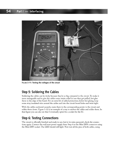
FIGURE 3-11: Testing the voltages of the circuit
Step 5: Soldering the Cables
Soldering the cables can be tricky because they’re so big compared to the circuit. To make it
more manageable and to give the cables some strain-relief in case they get pulled, hot glue
them to the edge of the board. For an extra bit of added protection, before hot gluing, loop
some stray insulated wire around the cables and into the circuit board holes and twist tight.
With the cables anchored securely, route them to the corresponding points in the circuit and
solder them down. Figure 3-12 is an example of a way to anchor the cables and solder them. In
that figure you can also see that I eventually opted for a socket for the IC.
Step 6: Testing Connections
The circuit is officially finished and ready to use, but to be extra paranoid, check the connec-
tions again. Connect the wall wart power supply from Step 4 to the Mini DIN connector using
the Mini DIN socket. The LED should still light. Now test all the pins of both cables, using