
Page 72 - Hacking Roomba
P. 72
Chapter 3 — Building a Roomba Serial Interface Tether 53
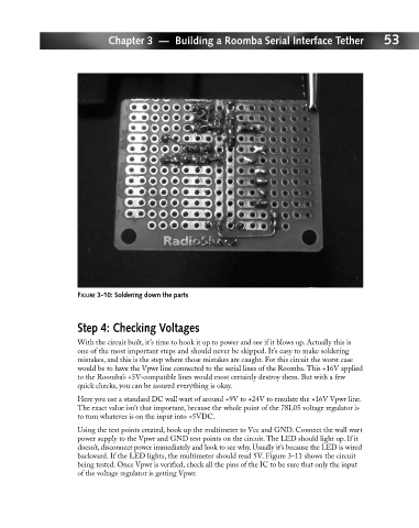
FIGURE 3-10: Soldering down the parts
Step 4: Checking Voltages
With the circuit built, it’s time to hook it up to power and see if it blows up. Actually this is
one of the most important steps and should never be skipped. It’s easy to make soldering
mistakes, and this is the step where those mistakes are caught. For this circuit the worst case
would be to have the Vpwr line connected to the serial lines of the Roomba. This +16V applied
to the Roomba’s +5V-compatible lines would most certainly destroy them. But with a few
quick checks, you can be assured everything is okay.
Here you use a standard DC wall wart of around +9V to +24V to emulate the +16V Vpwr line.
The exact value isn’t that important, because the whole point of the 78L05 voltage regulator is
to turn whatever is on the input into +5VDC.
Using the test points created, hook up the multimeter to Vcc and GND. Connect the wall wart
power supply to the Vpwr and GND test points on the circuit. The LED should light up. If it
doesn’t, disconnect power immediately and look to see why. Usually it’s because the LED is wired
backward. If the LED lights, the multimeter should read 5V. Figure 3-11 shows the circuit
being tested. Once Vpwr is verified, check all the pins of the IC to be sure that only the input
of the voltage regulator is getting Vpwr.