
Page 70 - Hacking Roomba
P. 70
Chapter 3 — Building a Roomba Serial Interface Tether 51
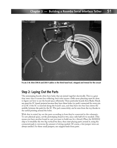
FIGURE 3-8: Mini DIN 8 and DB-9 cables in the third-hand tool, stripped and tinned for the circuit
Step 2: Laying Out the Parts
The prototyping boards often have holes that are joined together electrically. This is a great
time saver since it means less soldering, but it also means a little more planning must be done
to figure out how to use the board space efficiently. These particular boards from Radio Shack
are great for IC-based projects because they have three holes (or pads) connected for every pin
of an IC if the IC is inserted along the board’s axis, and they have two bus lines down the
middle, between the pads for the IC. The pad connectivity can be seen from the top thanks to
the useful printing around the holes.
With that in mind, lay out the parts according to how they’re connected in the schematic.
To save physical space, cut the prototyping board in two, since only half of it is needed. (This
means you have another board in case you want to build one for a friend.) Place the MAX232
chip so it straddles the two big vertical bus lines, then start placing parts around it, using the
connected pads to minimize the amount of wiring needed. Of course, a few jumper wires are
always needed. For these small jumpers, use snipped leads from parts.