
Page 66 - Hacking Roomba
P. 66
Chapter 3 — Building a Roomba Serial Interface Tether 47
VCC
LED1 green
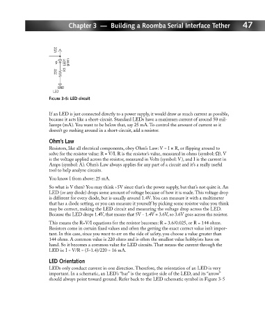
220' R1
GND
LED
FIGURE 3-5: LED circuit
If an LED is just connected directly to a power supply, it would draw as much current as possible,
because it acts like a short-circuit. Standard LEDs have a maximum current of around 50 mil-
liamps (mA). You want to be below that, say 25 mA. To control the amount of current so it
doesn’t go rushing around in a short-circuit, add a resistor.
Ohm’s Law
Resistors, like all electrical components, obey Ohm’s Law: V = I × R, or flipping around to
solve for the resistor value: R = V/I. R is the resistor’s value, measured in ohms (symbol: Ω). V
is the voltage applied across the resistor, measured in Volts (symbol: V), and I is the current in
Amps (symbol: A). Ohm’s Law always applies for any part of a circuit and it’s a really useful
tool to help analyze circuits.
You know I from above: 25 mA.
So what is V then? You may think +5V since that’s the power supply, but that’s not quite it. An
LED (or any diode) drops some amount of voltage because of how it is made. This voltage drop
is different for every diode, but is usually around 1.4V. You can measure it with a multimeter
that has a diode setting, or you can measure it yourself by picking some resistor value you think
may be correct, making the LED circuit and measuring the voltage drop across the LED.
Because the LED drops 1.4V, that means that 5V - 1.4V = 3.6V, so 3.6V goes across the resistor.
This means the R=V/I equations for the resistor becomes: R = 3.6/0.025, or R = 144 ohms.
Resistors come in certain fixed values and often the getting the exact correct value isn’t impor-
tant. In this case, since you want to err on the side of safety, you choose a value greater than
144 ohms. A common value is 220 ohms and is often the smallest value hobbyists have on
hand. So it becomes a common value for LED circuits. That means the current through the
LED is: I = V/R = (5-1.4)/220 = 16 mA.
LED Orientation
LEDs only conduct current in one direction. Therefore, the orientation of an LED is very
important. In a schematic, an LED’s “bar” is the negative side of the LED, and its “arrow”
should always point toward ground. Refer back to the LED schematic symbol in Figure 3-5