
Page 69 - Hacking Roomba
P. 69
50 Part I — Interfacing
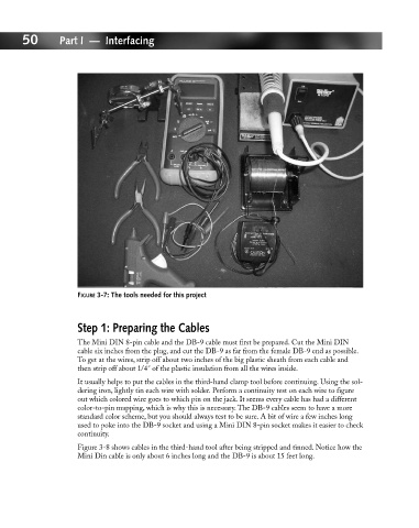
FIGURE 3-7: The tools needed for this project
Step 1: Preparing the Cables
The Mini DIN 8-pin cable and the DB-9 cable must first be prepared. Cut the Mini DIN
cable six inches from the plug, and cut the DB-9 as far from the female DB-9 end as possible.
To get at the wires, strip off about two inches of the big plastic sheath from each cable and
then strip off about 1/4˝ of the plastic insulation from all the wires inside.
It usually helps to put the cables in the third-hand clamp tool before continuing. Using the sol-
dering iron, lightly tin each wire with solder. Perform a continuity test on each wire to figure
out which colored wire goes to which pin on the jack. It seems every cable has had a different
color-to-pin mapping, which is why this is necessary. The DB-9 cables seem to have a more
standard color scheme, but you should always test to be sure. A bit of wire a few inches long
used to poke into the DB-9 socket and using a Mini DIN 8-pin socket makes it easier to check
continuity.
Figure 3-8 shows cables in the third-hand tool after being stripped and tinned. Notice how the
Mini Din cable is only about 6 inches long and the DB-9 is about 15 feet long.