
Page 238 - Handbook Of Multiphase Flow Assurance
P. 238
Hydrate stability and crystal growth 237
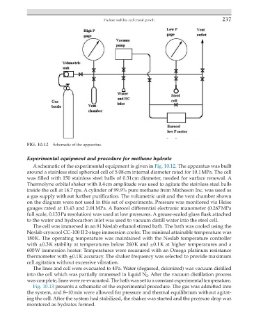
FIG. 10.12 Schematic of the apparatus.
Experimental equipment and procedure for methane hydrate
A schematic of the experimental equipment is given in Fig. 10.12. The apparatus was built
around a stainless steel spherical cell of 5.08 cm internal diameter rated for 10.1 MPa. The cell
was filled with 150 stainless steel balls of 0.31 cm diameter, needed for surface renewal. A
Thermolyne orbital shaker with 0.4 cm amplitude was used to agitate the stainless steel balls
inside the cell at 16.7 rps. A cylinder of 99.9% pure methane from Matheson Inc. was used as
a gas supply without further purification. The volumetric unit and the vent chamber shown
on the diagram were not used in this set of experiments. Pressure was monitored via Heise
gauges rated at 13.43 and 2.01 MPa. A Barocel differential electronic manometer (0.267 MPa
full scale, 0.133 Pa resolution) was used at low pressures. A grease-sealed glass flask attached
to the water and hydrocarbon inlet was used to vacuum distill water into the steel cell.
The cell was immersed in an 8 l Neslab ethanol stirred bath. The bath was cooled using the
Neslab cryocool CC-100 II 2-stage immersion cooler. The minimal attainable temperature was
180 K. The operating temperature was maintained with the Neslab temperature controller
with ±0.3 K stability at temperatures below 260 K and ±0.1 K at higher temperatures and a
600 W immersion heater. Temperatures were measured with an Omega platinum resistance
thermometer with ±0.1 K accuracy. The shaker frequency was selected to provide maximum
cell agitation without excessive vibration.
The lines and cell were evacuated to 4 Pa. Water (degassed, deionized) was vacuum distilled
into the cell which was partially immersed in liquid N 2 . After the vacuum distillation process
was complete, lines were re-evacuated. The bath was set to a constant experimental temperature.
Fig. 10.13 presents a schematic of the experimental procedure. The gas was admitted into
the system, and 8–10 min were allowed for pressure and thermal equilibrium without agitat-
ing the cell. After the system had stabilized, the shaker was started and the pressure drop was
monitored as hydrates formed.