
Page 213 - Handbook of Battery Materials
P. 213
182 6 Lead Oxides
10 µm 10 µm
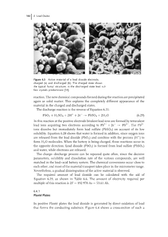
Figure 6.3 Active material of a lead dioxide electrode,
charged (a) and discharged (b). The charged state shows
the typical ‘lump’ structure; in the discharged state lead sul-
fate crystals predominate [14].
reaction. The new chemical compounds formed during the reaction are precipitated
again as solid matter. This explains the completely different appearance of the
material in the charged and discharged states.
The discharge reaction is the reverse of Equation 6.21:
PbO 2 + H 2 SO 4 + 2H + 2e → PbSO 4 + 2H 2 O (6.29)
+
−
In this reaction at the positive electrode bivalent lead ions are formed by tetravalent
2+
−
lead ions acquiring two electrons according to Pb 4+ + 2e → Pb . The Pb 2+
ions dissolve but immediately form lead sulfate (PbSO 4 ) on account of its low
solubility. Equation 6.28 shows that water is formed in addition, since oxygen ions
are released from the lead dioxide (PbO 2 ) and combine with the protons (H )to
+
form H 2 O molecules. When the battery is being charged, these reactions occur in
the opposite direction. Lead dioxide (PbO 2 ) is formed from lead sulfate (PbSO 4 )
and water, while electrons are released.
The charge–discharge process can be repeated quite often, since the decisive
parameters, solubility and dissolution rate of the various compounds, are well
matched in the lead–acid battery system. The chemical conversions occur close to
each other, and most of the material transport takes place in the micrometer range.
Nevertheless, a gradual disintegration of the active material is observed.
The required amount of lead dioxide can be calculated with the aid of
Equation 6.29, as shown in Table 6.6. The amount of electricity required per
multiple of this reaction is 2F = 192 970 As = 53.61 Ah.
6.4.1
Plant´ e Plates
In positive Plant´ e plates the lead dioxide is generated by direct oxidation of lead
that forms the conducting substrate. Figure 6.4 shows a cross-section of such a