
Page 455 - Handbook of Battery Materials
P. 455
14.11 Solid Electrolyte Matrix Electrode Structures 427
1000
800
EMF (mV vs. Li) 600 Li-Sn
400
200
Li-Cd
0
0 1 2 3 4 5
x in Li x Cd, Li x Sn
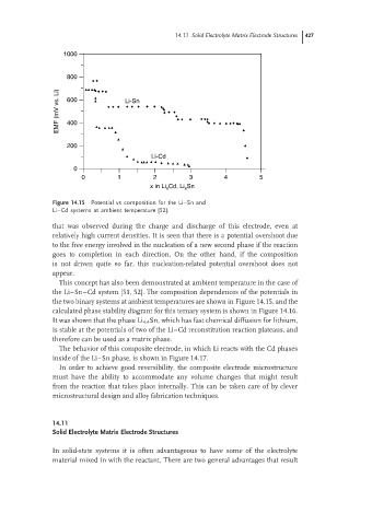
Figure 14.15 Potential vs composition for the Li–Sn and
Li–Cd systems at ambient temperature [52].
that was observed during the charge and discharge of this electrode, even at
relatively high current densities. It is seen that there is a potential overshoot due
to the free energy involved in the nucleation of a new second phase if the reaction
goes to completion in each direction. On the other hand, if the composition
is not driven quite so far, this nucleation-related potential overshoot does not
appear.
This concept has also been demonstrated at ambient temperature in the case of
the Li–Sn–Cd system [51, 52]. The composition dependences of the potentials in
the two binary systems at ambient temperatures are shown in Figure 14.15, and the
calculated phase stability diagram for this ternary system is shown in Figure 14.16.
It was shown that the phase Li 4.4 Sn, which has fast chemical diffusion for lithium,
is stable at the potentials of two of the Li–Cd reconstitution reaction plateaus, and
therefore can be used as a matrix phase.
The behavior of this composite electrode, in which Li reacts with the Cd phases
inside of the Li–Sn phase, is shown in Figure 14.17.
In order to achieve good reversibility, the composite electrode microstructure
must have the ability to accommodate any volume changes that might result
from the reaction that takes place internally. This can be taken care of by clever
microstructural design and alloy fabrication techniques.
14.11
Solid Electrolyte Matrix Electrode Structures
In solid-state systems it is often advantageous to have some of the electrolyte
material mixed in with the reactant. There are two general advantages that result