
Page 25 - Handbook of Biomechatronics
P. 25
18 Ahmed R. Arshi
P=e¥f
Direction of half
e arrow
Direction of effort
e
System A System B
f
Direction of flow
f
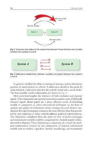
Fig. 2 Schematic description of the relationship between Power direction and causality
between two systems A and B.
System A System B
Fig. 3 Alternative relationships between causality and power between two systems
A and B.
In general, whether the effort is entering or leaving a system determines
position of causal strokes on a bond. A distinction should at this point be
made between a half arrow placed at the end of a bond and a causal stroke.
The four possible causal combinations are shown in Fig. 3.
Here each bond implies the existence of both excitation and response
signals. This is important since power interactions require a pair of bilaterally
oriented signals. Bond graphs are a more efficient means of describing
models in comparison to other conventional techniques on the basis of
quantity and quality of information which is being conveyed. System visu-
alization through bond graph notation is far more effective than that permit-
ted by state equations or other multidisciplinary graphical representations.
The subsystems considered from the point of view of power exchanges
and external port variables could be categorized by a limited number of fun-
damental multiports. These functioning components of a model are ideal-
ized mathematical versions of real components of material and physical
models such as resistive, capacitive, inertial, transducing, and transmission