
Page 24 - Handbook of Biomechatronics
P. 24
Introduction 17
simple linguistic phrases are often used in crucial coupling junctions. The
multitudes of connections in biomechatronic systems could thus result in a
nonuniform combination of schematic diagrams, equations, words, and
semipictorial representations.
11 MECHANISM OF INTERCONNECTIONS
The bond graph technology used for studying dynamic systems con-
sists of subsystems linked together by “lines” representing power bonds.
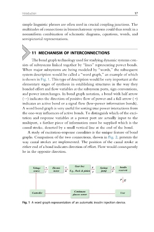
When major subsystems are being modeled by “words,” the subsequent
system description would be called a “word graph,” an example of which
is shown in Fig. 1. This type of description would be very important at the
elementary stages of synthesis in establishing structures in the way they
bonded effort and flow variables at the subsystem ports, sign conventions,
and power interchanges. In bond graph notation, a bond with half arrow
(*) indicates the direction of positive flow of power and a full arrow (⇢)
indicates an active bond or a signal flow (low-power information bonds).
A word bond graph is very useful for sorting true power interactions from
the one-way influences of active bonds. To distinguish which of the exci-
tation and response variables at a power port are actually input to the
multiport, a further piece of information must be supplied which is the
causal stroke, denoted by a small vertical line at the end of the bond.
A study of excitation-response causalities is the unique feature of bond
graphs. Comparison of the two connections, shown in Fig. 2, presents the
way causal strokes are implemented. The position of the causal stroke at
either end of a bond indicates direction of effort. Flow would consequently
be in the opposite direction.
Voltage v Electric t Gear box F Syringe F Insulin
source motor w E.g., Rack & pinion pump V reservoir
i V
P Q
Continuous
Controller User
glucose sensor
Fig. 1 A word graph representation of an automatic insulin injection device.