Page 557 - Handbook of Biomechatronics
P. 557
550                                                    Graham Brooker


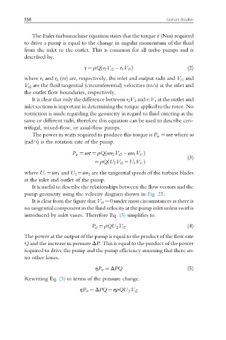
             The Euler turbomachine equation states that the torque τ (Nm) required
          to drive a pump is equal to the change in angular momentum of the fluid
          from the inlet to the outlet. This is common for all turbo pumps and is
          described by.

                                       ð
                                 τ ¼ ρQr 2 V t2  r 1 V t1 Þ             (2)
          where r 1 and r 2 (m) are, respectively, the inlet and output radii and V t1 and
          V t2 are the fluid tangential (circumferential) velocities (m/s) at the inlet and
          the outlet flow boundaries, respectively.
             It is clear that only the difference between r 2 V 2 and r 1 V 1 at the outlet and
          inlet sections is important in determining the torque applied to the rotor. No
          restriction is made regarding the geometry in regard to fluid entering at the
          same or different radii, therefore this equation can be used to describe cen-
          trifugal, mixed-flow, or axial-flow pumps.
             The power in watts required to produce this torque is P w ¼ ωτ where ω
          (rad/s) is the rotation rate of the pump.

                                         ð
                             P w ¼ ωτ ¼ ρQ ωr 2 V t2  ωr 1 V t1 Þ
                                                                        (3)
                                     ¼ ρQU 2 V t2  U 1 V t1 Þ
                                          ð
          where U 1 ¼ωr 1 and U 2 ¼ωr 2 are the tangential speeds of the turbine blades
          at the inlet and outlet of the pump.
             It is useful to describe the relationships between the flow vectors and the
          pump geometry using the velocity diagram shown in Fig. 25.
             It is clear from the figure that V t1 ¼0 under most circumstances as there is
          no tangential component in the fluid velocity at the pump inlet unless swirl is
          introduced by inlet vanes. Therefore Eq. (3) simplifies to.

                                    P w ¼ ρQU V t2                      (4)
                                             2
          The power at the output of the pump is equal to the product of the flow rate
          Q and the increase in pressure ΔP. This is equal to the product of the power
          required to drive the pump and the pump efficiency assuming that there are
          no other losses.
                                     ηP w ¼ ΔPQ                         (5)

          Rewriting Eq. (3) in terms of the pressure change.

                                ηP w ¼ ΔPQ ¼ ηρQU V t2
                                                  2

