
Page 558 - Handbook of Biomechatronics
P. 558
Artificial Hearts 551
→
V 2 V
V rb2 V n2 t2 →
V rb2 U = r w b a 2 V 2
2
2
b 2 2
U 2
Velocity components
V rb1 at the outlet
b
r 2 1
→
V 1
V t1
V V →
r 1 rb1 n1 V 1
= r w a
U 1 1 b 1 1
U
Absolute velocity as the sum 1
of the velocity relative to the Velocity components
blade and rotor velocity at the inlet
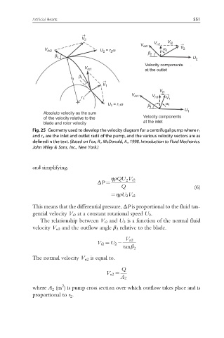
Fig. 25 Geometry used to develop the velocity diagram for a centrifugal pump where r 1
and r 2 are the inlet and outlet radii of the pump, and the various velocity vectors are as
defined in the text. (Based on Fox, R., McDonald, A., 1998. Introduction to Fluid Mechanics.
John Wiley & Sons, Inc., New York.)
and simplifying.
ηρQU V t2
2
ΔP ¼
Q (6)
¼ ηρU 2 V t2
This means that the differential pressure, ΔP is proportional to the fluid tan-
gential velocity V t2 at a constant rotational speed U 2 .
The relationship between V t2 and U 2 is a function of the normal fluid
velocity V n2 and the outflow angle β 2 relative to the blade.
V n2
V t2 ¼ U 2
tanβ 2
The normal velocity V n2 is equal to.
Q
V n2 ¼
A 2
2
where A 2 (m ) is pump cross section over which outflow takes place and is
proportional to r 2 .