
Page 560 - Handbook of Biomechatronics
P. 560
Artificial Hearts 553
20,000 1120
Axial flow pumps
Centrifugal flow pumps
15,000 840
Rotational speed (rpm) 10,000 560 Specific speed (ns)
Axial
5000 280
U 2 > 5.2 m/s
Centrifugal
U > 3.7 m/s
2
0
20 40 60 80
Impeller diameter (mm)
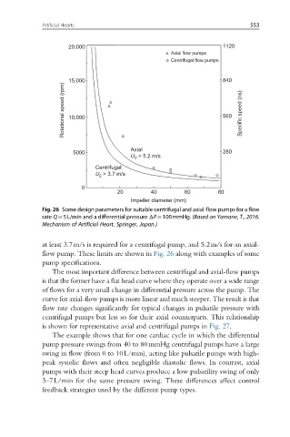
Fig. 26 Some design parameters for suitable centrifugal and axial-flow pumps for a flow
rate Q¼5L/min and a differential pressure ΔP¼100mmHg. (Based on Yamane, T., 2016.
Mechanism of Artificial Heart. Springer, Japan.)
at least 3.7m/s is required for a centrifugal pump, and 5.2m/s for an axial-
flow pump. These limits are shown in Fig. 26 along with examples of some
pump specifications.
The most important difference between centrifugal and axial-flow pumps
is that the former have a flat head curve where they operate over a wide range
of flows for a very small change in differential pressure across the pump. The
curve for axial-flow pumps is more linear and much steeper. The result is that
flow rate changes significantly for typical changes in pulsatile pressure with
centrifugal pumps but less so for their axial counterparts. This relationship
is shown for representative axial and centrifugal pumps in Fig. 27.
The example shows that for one cardiac cycle in which the differential
pump pressure swings from 40 to 80mmHg centrifugal pumps have a large
swing in flow (from 0 to 10L/min), acting like pulsatile pumps with high-
peak systolic flows and often negligible diastolic flows. In contrast, axial
pumps with their steep head curves produce a low pulsatility swing of only
3–7L/min for the same pressure swing. These differences affect control
feedback strategies used by the different pump types.