
Page 591 - Handbook of Biomechatronics
P. 591
582 Graham Brooker
Sensing and pacing can be accomplished using one of two different con-
figurations: bipolar and unipolar. In bipolar, the anode and the cathode are
close together, with the anode at the tip of the lead and the cathode as a ring
about 2cm back from the tip. In unipolar, the anode and the cathode can be
5–10cm apart with the anode being the lead tip, and the cathode, the hous-
ing of pulse generator itself (usually in the pectoral region). In terms of pac-
ing performance, they produce similar results, but in terms of sensing, the
unipolar configuration is more likely to sense noncardiac signals, particularly
myoelectric signals. Most of the new-generation pacemakers can be config-
ured to sense and pace in either configuration.
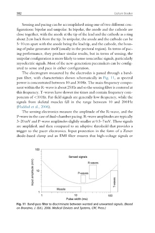
The electrogram measured by the electrodes is passed through a band-
pass filter, with characteristics shown schematically in Fig. 11, as spectral
power is concentrated between 10 and 30Hz. The main frequency compo-
nent within the R-wave is about 25Hz and so the sensing filter is centered at
this frequency. T-waves have slower rise times and contain frequency com-
ponents of <10Hz. Far-field signals are generally low frequency, while the
signals from skeletal muscles fall in the range between 10 and 200Hz
(Haddad et al., 2006).
The sensing electronics measure the amplitude of the R-wave, and the
P-wave in the case of dual-chamber pacing. R-wave amplitudes are typically
3–20mV and P-wave amplitudes slightly smaller at 0.5–7mV. These signals
are amplified, and then compared to an adaptive threshold that provides a
trigger to the pacer electronics. Input protection in the form of a Zener
diode-based clamp and an EMI filter ensures that high-voltage signals or
Fig. 11 Band-pass filter to discriminate between wanted and unwanted signals. (Based
on Bronzino, J. (Ed.), 2006. Medical Devices and Systems, CRC Press.)