
Page 594 - Handbook of Biomechatronics
P. 594
Pacemakers 585
circuitry, among others. Improvements in lead design have also had a major
effect on battery life. In the 1960s effective stimulation required a pulse gen-
erator output of 675 μJ, while modern leads only require only 3–6 μJ, a
reduction of more than 100 times (Bronzino, 2006).
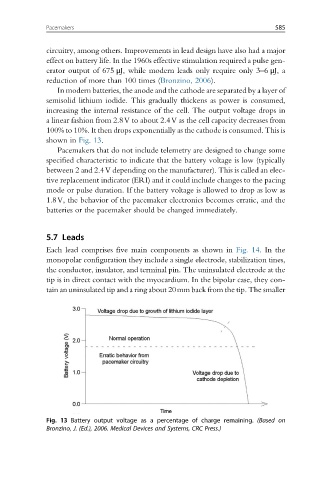
In modern batteries, the anode and the cathode are separated by a layer of
semisolid lithium iodide. This gradually thickens as power is consumed,
increasing the internal resistance of the cell. The output voltage drops in
a linear fashion from 2.8V to about 2.4V as the cell capacity decreases from
100% to 10%. It then drops exponentially as the cathode is consumed. This is
shown in Fig. 13.
Pacemakers that do not include telemetry are designed to change some
specified characteristic to indicate that the battery voltage is low (typically
between 2 and 2.4V depending on the manufacturer). This is called an elec-
tive replacement indicator (ERI) and it could include changes to the pacing
mode or pulse duration. If the battery voltage is allowed to drop as low as
1.8V, the behavior of the pacemaker electronics becomes erratic, and the
batteries or the pacemaker should be changed immediately.
5.7 Leads
Each lead comprises five main components as shown in Fig. 14. In the
monopolar configuration they include a single electrode, stabilization tines,
the conductor, insulator, and terminal pin. The uninsulated electrode at the
tip is in direct contact with the myocardium. In the bipolar case, they con-
tain an uninsulated tip and a ring about 20mm back from the tip. The smaller
Fig. 13 Battery output voltage as a percentage of charge remaining. (Based on
Bronzino, J. (Ed.), 2006. Medical Devices and Systems, CRC Press.)