
Page 595 - Handbook of Biomechatronics
P. 595
586 Graham Brooker
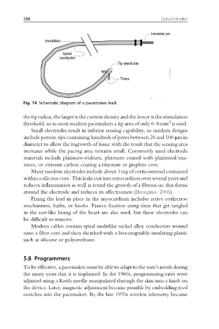
Fig. 14 Schematic diagram of a pacemaker lead.
the tip radius, the larger is the current density and the lower is the stimulation
2
threshold, so in most modern pacemakers a tip area of only 6–8mm is used.
Small electrodes result in inferior sensing capability, so modern designs
include porous-tips containing hundreds of pores between 20 and 100 μmin
diameter to allow the ingrowth of tissue with the result that the sensing area
increases while the pacing area remains small. Commonly used electrode
materials include platinum-iridium, platinum coated with platinized tita-
nium, or vitreous carbon coating a titanium or graphite core.
Many modern electrodes include about 1mg of corticosteroid contained
within a silicone core. This leaks out into myocardium over several years and
reduces inflammation as well as retard the growth of a fibrous sac that forms
around the electrode and reduces its effectiveness (Bronzino, 2006).
Fixing the lead in place in the myocardium includes active corkscrew
mechanisms, barbs, or hooks. Passive fixation using tines that get tangled
in the net-like lining of the heart are also used, but these electrodes can
be difficult to remove.
Modern cables contain spiral multifilar nickel alloy conductors wound
onto a fiber core and then sheathed with a biocompatible insulating plastic
such as silicone or polyurethane.
5.8 Programmers
To be effective, a pacemaker must be able to adapt to the user’s needs during
the many years that it is implanted. In the 1960s, programming rates were
adjusted using a Keith needle manipulated through the skin into a knob on
the device. Later, magnetic adjustment became possible by embedding reed
switches into the pacemaker. By the late 1970s wireless telemetry became