
Page 593 - Handbook of Biomechatronics
P. 593
584 Graham Brooker
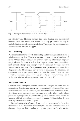
Fig. 12 Voltage multiplier circuit used in a pacemaker.
for refractory and blanking periods; the pulse duration and the interval
between atrial and ventricular events. Runaway protection circuitry is
included in the case of component failure. This limits the maximum pulse
rate to between 180 and 200ppm.
5.5 Telemetry
Pacemakers are capable of both transmitting and receiving information via a
wireless telemetry link. This two-way communication has a baud rate of
about 300bps. The pacemaker can provide real-time information on pulse
amplitude and duration, as well as lead impedance and battery condition,
lead current, charge, and energy. The programmer provides encoded
instructions to alter any of the programmable parameters and to retrieve
diagnostic data. These signals are encoded to minimize the likelihood of
extraneous interference signals reprogramming the device. There are con-
cerns that inadequate password protection and encryption are incorporated
in the link which is allowing pacemakers to be “hacked.”
5.6 Power Source
Over the years, a range of different battery technologies has been tried in
pacemakers, these include mercury-zinc, rechargeable silver-modified mer-
curic oxide-zinc, nickel-cadmium, and even radioactive plutonium batte-
ries. Some were associated with corrosion and early failure while others
produced hydrogen and required venting. Early batteries lasted weeks or
months, which is insignificant compared to modern lithium-iodide devices
with reported lives of up to 15 years.
Battery longevity is, of course, determined to a large extent by the activ-
ity expected of the pacemaker electronics; this includes pulse amplitude and
duration, single or dual chamber pacing, and power use by the sensing