
Page 204 - Handbook of Civil Engineering Calculations, Second Edition
P. 204
HANGERS, CONNECTORS, AND WIND-STRESS ANALYSIS 1.187
The shear factor equals the ratio of
the average width of the adjacent aisles
to the total width. Or, line A, 15/75
0.20; line B, (15 + 12)/75 0.36; line C,
(12 + 10.5)/75 0.30; line D, 10.5/75
0.14. For convenience, record these val-
ues in Fig. 15.
2. Compute the shear
in each column
For instance, column A-2-3, H
–3900(0.20) –780 lb (–3.5 kN); col-
umn C-1-2, H –(3900 + 7500)0.30
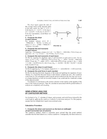
–3420 lb (–15.2 kN). FIGURE 16
3. Compute the end moments
of each column
1
Apply Eq. c. For instance, column A-2-3, M /2(–780)15 –5850 ft·lb (–7932.6 N·m); col-
umn D-0-1, M /2(–2751)18 –24,759 ft·lb (–33,573.2 N·m).
1
4. Compute the end moments of each beam
Do this by equating the algebraic sum of end moments at each joint to zero. For in-
stance, at line 3: M AB 5850 ft·lb (7932.6 N·m); M BC –5850 + 10,530 4680 ft·lb
(6346.1 N·m); M CD –4680 + 8775 4095 ft·lb (5552.8 N·m). At line 2: M AB 5850
+ 17,100 22,950 ft·lb (31,120.2 N·m); M BC –22,950 + 30,780 + 10,530 18,360
ft·lb (24,896.0 N·m).
5. Compute the shear in each beam
Do this by applying Eq. b. For instance, beam B-2-C, V 2(18,360)724 1530 lb (6.8 kN).
6. Compute the axial force in each member
Do this by drawing free-body diagrams of the joints and applying the equations of equi-
librium. It is found that the axial forces in the interior columns are zero. This condition
stems from the first assumption underlying the portal method and the fact that each interi-
or column functions as both the leeward column of one portal and the windward column
of the adjacent portal.
The absence of axial forces in the interior columns in turn results in the equality of the
shear in the beams at each tier. Thus, the calculations associated with the portal method of
analysis are completely self-checking.
WIND-STRESS ANALYSIS
BY CANTILEVER METHOD
For the bent in Fig. 17, calculate all shears, end moments, and axial forces induced by the
wind loads by applying the cantilever method of wind-stress analysis. For this purpose,
assume that the columns have equal cross-sectional areas.
Calculation Procedure:
1. Compute the shear and moment on the bent at midheight
of each horizontal row of columns
The cantilever method, which is somewhat more rational than the portal method,
considers that the bent behaves as a vertical cantilever. Consequently, the direct stress in a