Page 199 - Handbook of Civil Engineering Calculations, Second Edition
P. 199

1.182           STRUCTURAL STEEL ENGINEERING AND DESIGN

                                                           Recording the allowable stresses and modular
                                                        ratio by using the ACI  Code, we get  p   750
                                                        lb/sq.in. (5170 kPa) and n   9. From the AISC
                                                        Specification, f s   14,000 lb/sq.in. (96.5 MPa);
                                                        the allowable bending stress in the plate is 27,000
                                                        lb/sq.in. (186.1 MPa).
                                                        2. Construct the stress
                                                        and force diagrams
                                                        These are shown in Fig. 13. Then f s /n   14/9
                                                        1.555 kips/sq.in. (10.7 MPa);  kd   23(0.750/
                                                        2.305)   7.48 in. (190.0 mm); jd   23 – 7.48/3
                                                        20.51 in. (521.0 mm).
                                                        3. Design the base plate
                                                                  1
                                                        Thus,  C   /2(7.48)(0.750B)    2.805B. Take
                                                        moments with respect to the anchor bolt, or  M
                                                          30(10) + 1100 – 2.805B(20.51)   0; B   24.3
                                                        in. (617.2 mm).
                                                           Assume that the critical bending stress in the
                                                        base plate occurs at the face of the column. Com-
                                                        pute the bending moment at the face for a 1-in.
                                                        (25.4-mm) width of plate. Referring to Fig. 13c,
                                                        we have p
  0.750(1.48/7.48)   0.148 kips/sq.in.
                                                        (1020.3 kPa); M   (6 /6)(0.148 + 2   0.750)
                                                                        2
                                                                           2
                                                        9.89 in.·kips (1.12 kN·m); t – 6M/27   2.20 sq.in.
                                                                2
                                                        (14.19 cm );  t   1.48 in. (37.6 mm). Make the
                                                                                    1
                                                        base plate 25 in. (635 mm) wide and 1 /2 in. (38.1
                                                        mm) thick.
                                                        4. Design the anchor bolts
                                                        From the calculation in step 3,  C   2.805B
                                                        2.805(24.3)   68.2 kips (303.4 kN); T   68.2 – 30
                                                          38.2 kips (169.9 kN); A s   38.2/14 – 2.73 sq.in.
                                                                2
                                                                                          1
                                                        (17.61 cm ). Refer to the AISC Manual. Use 2 /4-
                                                        in. (57.2-mm) anchor bolts, one on each side of the
                                                                                    2
                                                        flange. Then A s   3.02 sq.in. (19.48 cm ).
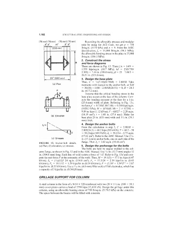
                            FIGURE 12. Anchor-bolt details.
                            (a) Plan; (b) elevation; (c) stresses.  5. Design the anchorage for the bolts
                                                        The bolts are held by angles welded to the col-
                            umn flange, as shown in Fig. 12 and in the AISC Manual. Use  /2-in. (12.7-mm) angles 12
                                                                        1
                            in. (304.8 mm) long. Each line of weld resists a force of  /2T. Refer to Fig. 13d and com-
                                                                     1
                            pute the unit force F at the extremity of the weld. Thus, M   19.1(3)   57.3 in.·kips (6.47
                                                            2
                                            2
                                      1
                            kN·m);  S x   ( /6)(12) 24 sq.in. (154.8 cm );  F x   57.3/24    2.39 kips/lin in. (0.43
                                                                              2
                                                                                   2 0.5
                            kN/mm); F y   19.1/12   1.59 kips/lin in (0.29 kN/mm); F   (2.39 + 1.59 )    2.87
                            kips/lin in. (0.52 kN/mm). Use a  /16-in. (4.8-mm) fillet weld of E60 electrodes, which has
                                                   5
                            a capacity of 3 kips/lin in. (0.54 kN/mm).
                            GRILLAGE SUPPORT FOR COLUMN
                            A steel column in the form of a W14   320 reinforced with two 20   1 /2 in. (508   38.1
                                                                               1
                            mm) cover plates carries a load of 2790 kips (12,410 kN). Design the grillage under this
                            column, using an allowable bearing stress of 750 lb/sq.in. (5170.5 kPa) on the concrete.
                            The space between the beams will be filled with concrete.
   194   195   196   197   198   199   200   201   202   203   204