
Page 195 - Handbook of Civil Engineering Calculations, Second Edition
P. 195
1.178 STRUCTURAL STEEL ENGINEERING AND DESIGN
The AISC Specification establishes the criteria for ascertaining whether column stiffeners
are required. The first criterion is obtained by equating the compressive stress in the col-
umn web at the toe of the fillet to the yield-point stress f y ; the second criterion was ob-
tained empirically. At the ultimate load, the capacity of the unreinforced web (0.503 +
5 1.25)0.430f y 2.904f y ; capacity of beam flange 3.52f y ; 0.4(A f ) 0.5 0.4(3.52) 0.5
0.750 > 0.671 in. (17.04 mm).
Stiffeners are therefore required opposite both flanges of the beam. The required area
2
1
is A st 3.52 – 2.904 0.616 sq.in. (3.97 cm ). Make the stiffener plates 3 /2 in. (88.9
mm) wide to match the beam flange. From the AISC, t min 3.5/8.5 0.41 in. (10.4 mm).
1
Use two 3 /2 /2 in. (88.9 12.7 mm) stiffener plates opposite both beam flanges.
1
3. Design the connection plate for the top flange
Compute the flange force by applying the total depth of the beam. Thus, F 1520/16.00
2
95 kips (422.6 kN); A 95/22 4.32 sq.in. (27.87 cm ).
Since the beam flange is 7 in. (177.8 mm) wide, use a plate 5 in. (127 mm) wide and
2
7 /8 in. (22.2 mm) thick, for which A 4.38 sq.in. (28.26 cm ). This plate is butt-welded to
the column flange and fillet-welded to the beam flange. In accordance with the AISC
5
13
Specification, the minimum weld size is /16 in. (7.94 mm) and the maximum size is /16
in. (20.6 mm). Use a /8-in. (15.9-mm) weld, which has a capacity of 6000 lb/lin in. (1051
5
N/mm). Then, length of weld 95/6 15.8 in. (401.3 mm), say 16 in. (406.4 mm). To
ensure that yielding of the joint at ultimate load will occur in the plate rather than in the
weld, the top plate is left unwelded for a distance approximately equal to its width, as
shown in Fig. 9.
4. Design the seat
The connection plate for the bottom flange requires the same area and length of weld as
does the plate for the top flange The stiffener plate and its connecting weld are designed
in the same manner as in the previous calculation procedure.
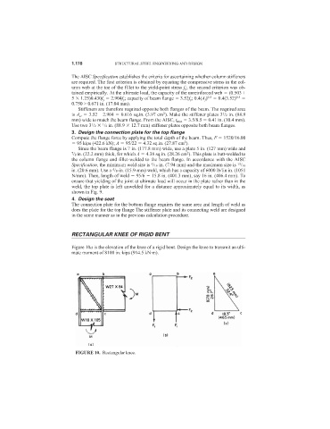
RECTANGULAR KNEE OF RIGID BENT
Figure 10a is the elevation of the knee of a rigid bent. Design the knee to transmit an ulti-
mate moment of 8100 in.·kips (914.5 kN·m).
FIGURE 10. Rectangular knee.