
Page 192 - Handbook of Civil Engineering Calculations, Second Edition
P. 192
HANGERS, CONNECTORS, AND WIND-STRESS ANALYSIS 1.175
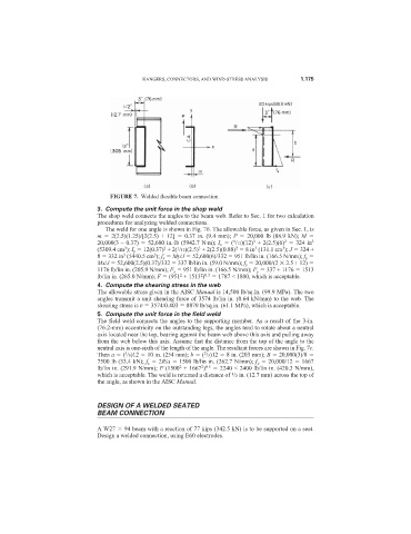
FIGURE 7. Welded flexible beam connection.
3. Compute the unit force in the shop weld
The shop weld connects the angles to the beam web. Refer to Sec. 1 for two calculation
procedures for analyzing welded connections.
The weld for one angle is shown in Fig. 7b. The allowable force, as given in Sec. 1, is
m 2(2.5)(1.25)/[2(2.5) + 12] 0.37 in. (9.4 mm); P 20,000 lb (88.9 kN); M
2
1
3
20,000(3 – 0.37) 52,600 in.·lb (5942.7 N·m); I x ( /12)(12) + 2(2.5)(6) 324 in 3
1
3
2
3
3
3
2
(5309.4 cm ); I y 12(0.37) + 2( /12)(2.5) + 2(2.5)(0.88) 8 in (131.1 cm ); J 324 +
3
8 332 in (5440.5 cm ); f x My/J 52,600(6)/332 951 lb/lin in. (166.5 N/mm); f y
3
Mx/J 52,600(2.5)(0.37)/332 337 lb/lin in. (59.0 N/mm); f y 20,000/(2 2.5 + 12)
1176 lb/lin in. (205.9 N/mm); F x 951 lb/lin in. (166.5 N/mm); F y 337 + 1176 1513
2
2 0.5
lb/lin in. (265.0 N/mm); F (951 + 1513 ) 1787 < 1800, which is acceptable.
4. Compute the shearing stress in the web
The allowable stress given in the AISC Manual is 14,500 lb/sq.in. (99.9 MPa). The two
angles transmit a unit shearing force of 3574 lb/lin in. (0.64 kN/mm) to the web. The
shearing stress is v 3574/0.403 8870 lb/sq.in. (61.1 MPa), which is acceptable.
5. Compute the unit force in the field weld
The field weld connects the angles to the supporting member. As a result of the 3-in.
(76.2-mm) eccentricity on the outstanding legs, the angles tend to rotate about a neutral
axis located near the top, bearing against the beam web above this axis and pulling away
from the web below this axis. Assume that the distance from the top of the angle to the
neutral axis is one-sixth of the length of the angle. The resultant forces are shown in Fig. 7c.
Then a ( /6)12 10 in. (254 mm); b ( /3)12 8 in. (203 mm); B 20,000(3)/8
5
2
7500 lb (33.4 kN); f x 2R/a 1500 lb/lin in. (262.7 N/mm); f y 20,000/12 1667
2 0.5
2
lb/lin in. (291.9 N/mm); F (1500 + 1667 ) 2240 < 2400 lb/lin in. (420.3 N/mm),
1
which is acceptable. The weld is returned a distance of /2 in. (12.7 mm) across the top of
the angle, as shown in the AISC Manual.
DESIGN OF A WELDED SEATED
BEAM CONNECTION
A W27 94 beam with a reaction of 77 kips (342.5 kN) is to be supported on a seat.
Design a welded connection, using E60 electrodes.