
Page 187 - Handbook of Civil Engineering Calculations, Second Edition
P. 187
1.170 STRUCTURAL STEEL ENGINEERING AND DESIGN
2
2
use the relation M u f y bd /4, or M p 36(0.5)(24) /4 2592 in.·kips (292.9 kN·m). This
is satisfactory.
6. Compare the ultimate direct force at section b-b
with the allowable value
Thus, P u 93.7 + 43.6 137.3 kips (610.7 kN); or P u 206.0 – 68.7 137.3 kips
2
(610.7 kN); e 9 – 2 7 in. (177.8 mm). By Eq. 2, x 9 + 7 – [(9 + 7) – 7 18] 0.5
4.6 in. (116.8 mm). By Eq. 1, P u,allow 36,000(0.5)(18 – 9.2) 158.4 kips (704.6 kN).
This is satisfactory.
On horizontal sections above a-a, the forces in the web members have not been com-
pletely transferred to the gusset plate, but the eccentricities are greater than those at a-a.
Therefore, the calculations in step 5 should be repeated with reference to one or two sec-
tions above a-a before any conclusion concerning the adequacy of the plate is drawn.
DESIGN OF A SEMIRIGID CONNECTION
A W14 38 beam is to be connected to the flange of a column by a semirigid connection
that transmits a shear of 25 kips (111.2 kN) and a moment of 315 in.·kips (35.6 kN·m).
Design the connection for the moment, using A141 shop rivets and A325 field bolts of
7 /8-in. (22.2-mm) diameter.
Calculation Procedure:
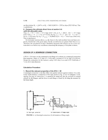
1. Record the relevant properties of the W14 38
A semirigid connection is one that offers only partial restraint against rotation. For a rela-
tively small moment, a connection of the type shown in Fig. 4a will be adequate. In de-
signing this type of connection, it is assumed for simplicity that the moment is resisted
entirely by the flanges; and the force in each flange is found by dividing the moment by
the beam depth.
FIGURE 4. (a) Semirigid connection; (b) deformation of flange angle.