
Page 186 - Handbook of Civil Engineering Calculations, Second Edition
P. 186
HANGERS, CONNECTORS, AND WIND-STRESS ANALYSIS 1.169
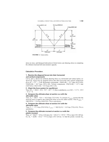
FIGURE 3. Gusset plate.
stress in shear, and disregard interaction of direct stress and shearing stress in computing
the ultimate-load and ultimate-moment capacity.
Calculation Procedure:
1. Resolve the diagonal forces into their horizontal
and vertical components
Let H u and V u denote the ultimate shearing force on a horizontal and vertical plane, re-
spectively. Resolving the diagonal forces into their horizontal and vertical components
2 0.5
2
gives (4 + 5 ) 6.40. Horizontal components: 150(4/6.40) 93.7 kips (416.8 kN);
110(4/6.40) 68.7 kips (305.6 kN). Vertical components: 150(5/6.40) 117.1 kips
(520.9 kN); 110(5/6.40) 85.9 kips (382.1 kN).
2. Check the force system for equilibrium
Thus, F H 206.0 – 43.6 – 93.7 – 68.7 0; this is satisfactory, as is F V 117.1 – 85.9
– 31.2 0.
3. Compare the ultimate shear at section a-a with the
allowable value
Thus, H u 206.0 – 43.6 162.4 kips (722.4 kN). To compute H u,allow assume that the
shearing stress is equal to the yield-point stress across the entire section. Then H u,allow
24(0.5)(18) 216 kips (960.8 kN). This is satisfactory.
4. Compare the ultimate shear at section b-b with the
allowable value
Thus, V u 117.1 kips (520.9 kN); V u,allow 18(0.5)(18) 162 kips (720.6 kN). This is
satisfactory.
5. Compare the ultimate moment at section a-a with the
plastic moment
Thus, cd 4(6)/5 4.8 in. (122 mm); M u 4.8(117.1 + 85.9) 974 in.·kips (110.1 kN·m).
Or, M u 6(206 – 43.6) 974 in.·kips (110.1 kN·m). To find the plastic moment M p ,