
Page 190 - Handbook of Civil Engineering Calculations, Second Edition
P. 190
HANGERS, CONNECTORS, AND WIND-STRESS ANALYSIS 1.173
2 0.5
2
(76.0 kN); F y 40/15 2.67 kips (11.9 kN); F (17.09 + 2.67 ) 17.30 < 17.65.
Therefore, this is acceptable.
4. Compute the stresses in the web plate at line 1
The plate is considered continuous; the rivet holes are assumed to be 1 in. (25.4 mm) in
diameter for the reasons explained earlier.
The total depth of the plate is 51 in. (1295.4 mm), the area and moment of inertia of
2
the net section are A n 0.416(51 – 15 1) 14.98 sq.in. (96.6 cm ) and I n
4
3
4
(1/12)(0.416)(51) – 1.0(0.416)(3510) 3138 in (130,603.6 cm ).
Apply the general shear equation. Since the section is rectangular, the maximum
shearing stress is v 1.5V/A n 1.5(40)/14.98 4.0 kips/sq.in. (27.6 MPa). The AISC
Specification gives an allowable stress of 14.5 kips/sq.in. (99.9 MPa).
The maximum flexural stress is f Mc/I n 2500(25.5)13138 20.3 < 27 kips/sq.in.
(186.1 MPa). This is acceptable. The use of 15 rivets is therefore satisfactory.
5. Compute the stresses in the rivets on line 2
The center of rotation of the angles cannot be readily located because it depends on the
amount of initial tension to which the rivets are subjected. For a conservative approximation,
assume that the center of rotation of the angles coincides with the horizontal centroidal axis
of the rivet group. The forces are F x 2500/[2(146.3)] 8.54 kips (37.9 kN); F y 40/30
1.33 kips (5.9 kN). The corresponding stresses in tension and shear are s t F y /A
8.54/0.6013 14.20 kips/sq.in. (97.9 MPa); s s F y /A 1.33/0.6013 2.21 kips/sq.in.
(15.2 MPa). The Specification gives s t,allow 28 – 1.6(2.21) > 20 kips/sq.in. (137.9 kPa).
This is acceptable.
6. Select the size of the connection angles
The angles are designed by assuming a uniform bending stress across a distance equal to
the spacing p of the rivets; the maximum stress is found by applying the tensile force on
the extreme rivet.
Try 4 4 /4 in. (102 102 19 mm) angles, with a standard gage of 2 /2 in. (63.5
1
3
mm) in the outstanding legs. Assuming the point of contraflexure to have the location
specified in the previous calculation procedure, we get c 0.6(2.5 – 0.75) 1.05 in.
1
2
(26.7 mm); M 8.54(1.05) 8.97 in.·kips (1.0 kN·m); f 8.97/[( /6)(3)(0.75) ] 31.9
> 27 kips/sq.in. (186.1 MPa). Use 5 5 /8 in. (127 127 22 mm) angles, with a
7
1
2 /2-in. (63.5-mm) gage in the outstanding legs.
7. Determine the number of rivets required on line 3
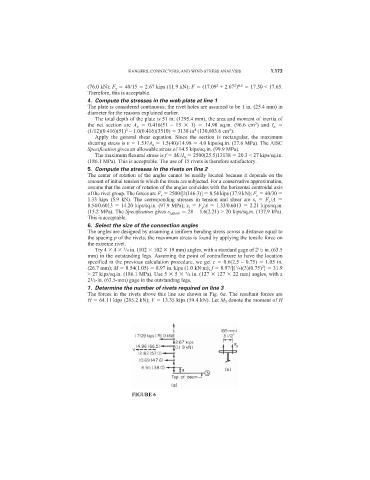
The forces in the rivets above this line are shown in Fig. 6a. The resultant forces are
H 64.11 kips (285.2 kN); V 13.35 kips (59.4 kN). Let M 3 denote the moment of H
FIGURE 6