
Page 194 - Handbook of Civil Engineering Calculations, Second Edition
P. 194
HANGERS, CONNECTORS, AND WIND-STRESS ANALYSIS 1.177
5
kips/lin in. Use a /16-in. (7.9-mm) weld, which has a capacity of 3 kips/lin in. (525.4
2
2
N/mm). Then F f 1 + f 2 130,300/L + 1029/L 3 . This equation is satisfied by L
2
2
4
2
14 in. (355.6 mm).
5. Determine the thickness of the stiffener plate
Assume this plate is triangular (Fig. 8d). The critical section for bending is assumed to co-
incide with the throat of the plate, and the maximum bending stress may be obtained by
2
applying f (P/tW sin )(1 + 6e
/W), where e
distance from center of seat to center
of bearing.
Using an allowable stress of 22,000 lb/sq.in. (151.7 MPa), we have e
e – 2.5
2
0.31 in. (7.9 mm), t {77/[22 5(14/14,87) ]}(1 + 6 0.31/5) 1.08 in. (27.4 mm).
1
Use a 1 /8-in. (28.6-mm) stiffener plate. The shearing stress in the plate caused by the
weld is v 2(3000)/1.125 5330 < 14,500 lb/sq.in. (99.9 MPa), which is acceptable.
DESIGN OF A WELDED
MOMENT CONNECTION
A W16 40 beam frames to the flange of a W12 72 column and transmits a shear of
42 kips (186.8 kN) and a moment of 1520 in.·kips (171.1 kN·m). Design a welded con-
nection, using E60 electrodes.
Calculation Procedure:
1. Record the relevant properties of the two sections
In designing a welded moment connection, it is assumed for simplicity that the beam
flanges alone resist the bending moment. Consequently, the beam transmits three forces
to the column: the tensile force in the top flange, the compressive force in the bottom
flange, and the vertical load. Although the connection is designed ostensibly on an elastic
design basis, it is necessary to consider
its behavior at ultimate load, since a
plastic hinge would form at this joint.
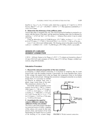
The connection is shown in Fig. 9.
Record the relevant properties of the
sections: for the W16 40, d 16.00 in.
(406.4 mm); b 7.00 in. (177.8 mm); t f
0.503 in. (12.8 mm); t w 0.307 in.
(7.8 mm); A f 7.00(0.503) 3.52 sq.in.
2
(22.7 cm ). For the W12 72, k 1.25
in. (31.8 mm); t f 0.671 in. (17.04 mm);
t w 0.403 in. (10.2 mm).
2. Investigate the need for
column stiffeners: design the
stiffeners if they are needed
The forces in the beam flanges introduce
two potential modes of failure: crippling
of the column web caused by the com-
pressive force, and fracture of the weld
transmitting the tensile force as a result
of the bending of the column flange. FIGURE 9. Welded moment connection.