
Page 193 - Handbook of Civil Engineering Calculations, Second Edition
P. 193
1.176 STRUCTURAL STEEL ENGINEERING AND DESIGN
Calculation Procedure:
1. Record the relevant properties of the beam
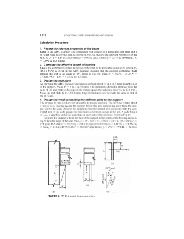
Refer to the AISC Manual. The connection will consist of a horizontal seat plate and a
stiffener plate below the seat, as shown in Fig. 8a. Record the relevant properties of the
W27 94: k 1.44 in. (36.6 mm); b 9.99 in. (253.7 mm); t f 0.747 in. (19.0 mm); t w
0.490 in. (12.4 mm).
2. Compute the effective length of bearing
Equate the compressive stress at the toe of the fillet to its allowable value of 27 kips/sq.in.
(186.1 MPa) as given in the AISC Manual. Assume that the reaction distributes itself
through the web at an angle of 45°. Refer to Fig. 8b. Then N P/27t w – k, or N
77/27(0.490) – 1.44 4.38 in. (111.3 mm).
3. Design the seat plate
1
As shown in the AISC Manual, the beam is set back about /2 in. (12.7 mm) from the face
of the support. Make W 5 in. (127.0 mm). The minimum allowable distance from the
5
edge of the seat plate to the edge of the flange equals the weld size plus /16 in. (7.8 mm).
Make the seat plate 12 in. (304.8 mm) long; its thickness will be made the same as that of
the stiffener.
4. Design the weld connecting the stiffener plate to the support
The stresses in this weld are not amenable to precise analysis. The stiffener rotates about
a neutral axis, bearing against the support below this axis and pulling away from the sup-
port above this axis. Assume for simplicity that the neutral axis coincides with the cen-
troidal axis of the weld group; the maximum weld stress occurs at the top. A weld length
of 0.2L is supplied under the seat plate on each side of the stiffener. Refer to Fig. 8c.
Compute the distance e from the face of the support to the center of the bearing, measur-
ing N from the edge of the seat. Thus, e W – N/2 5 – 4.38/2 2.81 in. (71.4 mm); P
3
77 kips (342.5 kN); M 77(2.81) 216.4 in.·kips (24.5 kN·m); m 0.417L; I x 0.25L f 1
2
3
Mc/I x 216.4(0.417L)/0.25L 361.0/L kips/lin in.; f 2 P/A 77/2.4L 32.08/L
FIGURE 8. Welded seated beam connection.