
Page 197 - Handbook of Civil Engineering Calculations, Second Edition
P. 197
1.180 STRUCTURAL STEEL ENGINEERING AND DESIGN
each member lies 84 in. (2133.6 mm)
from the section of tangency. Design the
knee.
Calculation Procedure:
1. Record the relevant properties
of the members
Refer to the Commentary in the AISC
Manual. The notational system is the
same as that used in the Manual, plus a
distance from section of contraflexure
to section of tangency; b member
flange width; x distance from section
of tangency to given section; M ulti-
mate moment at given section; M p
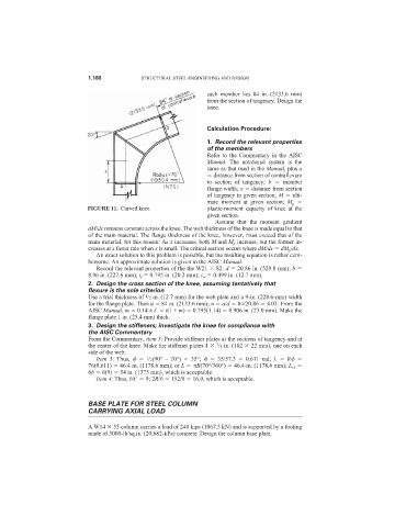
FIGURE 11. Curved knee. plastic-moment capacity of knee at the
given section.
Assume that the moment gradient
dM/dx remains constant across the knee. The web thickness of the knee is made equal to that
of the main material. The flange thickness of the knee, however, must exceed that of the
main material, for this reason: As x increases, both M and M p increase, but the former in-
creases at a faster rate when x is small. The critical section occurs where dM/dx dM p /dx.
An exact solution to this problem is possible, but the resulting equation is rather cum-
bersome. An approximate solution is given in the AISC Manual.
Record the relevant properties of the the W21 82: d 20.86 in. (529.8 mm); b
8.96 in. (227.6 mm); t f 0.795 in. (20.2 mm); t w 0.499 in. (12.7 mm).
2. Design the cross section of the knee, assuming tentatively that
flexure is the sole criterion
1
Use a trial thickness of /2 in. (12.7 mm) for the web plate and a 9-in. (228.6-mm) width
for the flange plate. Then a 84 in. (2133.6 mm); n a/d 84/20.86 4.03. From the
AISC Manual, m 0.14 ± t
t(1 + m) 0.795(1.14) 0.906 in. (23.0 mm). Make the
flange plate 1 in. (25.4 mm) thick.
3. Design the stiffeners; investigate the knee for compliance with
the AISC Commentary
From the Commentary, item 5: Provide stiffener plates at the sections of tangency and at
7
the center of the knee. Make the stiffener plates 4 /8 in. (102 22 mm), one on each
side of the web.
Item 3: Thus, /2(90° – 20°) 35°; 35/57.3 0.611 rad; L R
1
76(0.611) 46.4 in. (1178.6 mm); or L R(70°/360°) 46.4 in. (1178.6 mm); L cr
6b 6(9) 54 in. (1373 mm), which is acceptable.
Item 4: Thus, b/t
9; 2R/b 152/9 16.9, which is acceptable.
BASE PLATE FOR STEEL COLUMN
CARRYING AXIAL LOAD
A W14 53 column carries a load of 240 kips (1067.5 kN) and is supported by a footing
made of 3000-lb/sq.in. (20,682-kPa) concrete. Design the column base plate.