
Page 200 - Handbook of Civil Engineering Calculations, Second Edition
P. 200
HANGERS, CONNECTORS, AND WIND-STRESS ANALYSIS 1.183
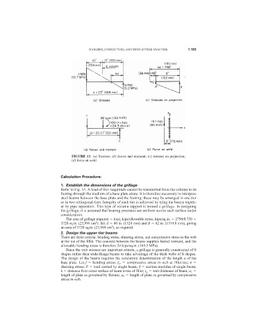
FIGURE 13. (a) Stresses; (b) forces and moment; (c) stresses on projection;
(d) force on weld.
Calculation Procedure:
1. Establish the dimensions of the grillage
Refer to Fig. 14. A load of this magnitude cannot be transmitted from the column to its
footing through the medium of a base plate alone. It is therefore necessary to interpose
steel beams between the base plate and the footing; these may be arranged in one tier
or in two orthogonal tiers. Integrity of each tier is achieved by tying the beams togeth-
er by pipe separators. This type of column support is termed a grillage. In designing
the grillage, it is assumed that bearing pressures are uniform across each surface under
consideration.
The area of grillage required load, kips/allowable stress, kips/sq.in. 2790/0.750
2
3720 sq.in. (23,994 cm ). Set A 60 in. (1524 mm) and B 62 in. (1574.8 mm), giving
2
an area of 3720 sq.in. (23,994 cm ), as required.
2. Design the upper-tier beams
There are three criteria: bending stress, shearing stress, and compressive stress in the web
at the toe of the fillet. The concrete between the beams supplies lateral restraint, and the
allowable bending stress is therefore 24 kips/sq.in. (165.5 MPa).
Since the web stresses are important criteria, a grillage is generally constructed of S
shapes rather than wide-flange beams to take advantage of the thick webs of S shapes.
The design of the beams requires the concurrent determination of the length a of the
base plate. Let f bending stress; f b , compressive stress in web at fillet toe; v
shearing stress; P load carried by single beam; S section modulus of single beam;
k distance from outer surface of beam to toe of fillet; t w web thickness of beam; a 1
length of plate as governed by flexure; a 2 length of plate as governed by compressive
stress in web.