
Page 201 - Handbook of Civil Engineering Calculations, Second Edition
P. 201
1.184 STRUCTURAL STEEL ENGINEERING AND DESIGN
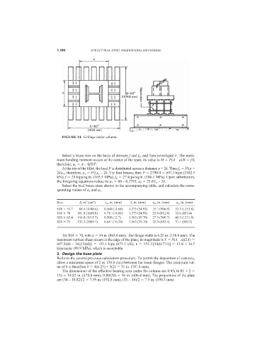
FIGURE 14. Grillage under column.
Select a beam size on the basis of stresses f and f b , and then investigate v. The maxi-
mum bending moment occurs at the center of the span; its value is M P(A – a)/8 fS;
therefore, a 1 A – 8fS/P.
At the toe of the fillet, the load P is distributed across a distance a + 2k. Then f b P/(a +
2k)t w ; therefore, a 2 P/f b t w – 2k. Try four beams; then P 2790/4 697.5 kips (3102.5
kN); f 24 kips/sq.in. (165.5 MPa); f b 27 kips/sq.in. (186.1 MPa). Upon substitution,
the foregoing equations reduce to a 1 60 – 0.2755; a 2 25.8/t w – 2k.
Select the trial beam sizes shown in the accompanying table, and calculate the corre-
sponding values of a 1 and a 2 .
3
3
Size S, in (cm ) t w , in. (mm) k, in. (mm) a 1 , in. (mm) a 2 , in. (mm)
S18 54.7 088.4 (1448.6) 0.460 (11.68) 1.375 (34.93) 35.7 (906.8) 53.3 (1353.8)
S18 70 101.9 (1669.8) 0.711 (18.06) 1.375 (34.93) 32.0 (812.8) 33.6 (853.4)0
S20 65.4 116.9 (1915.7) 0.500 (12.7)0 1.563 (39.70) 27.9 (708.7) 48.5 (1231.9)
S20 75 126.3 (2069.7) 0.641 (16.28) 1.563 (39.70) 25.3 (642.6) 37.1 (942.3)0
Try S18 70, with a 34 in. (863.6 mm). The flange width is 6.25 in. (158.8 mm). The
maximum vertical shear occurs at the edge of the plate; its magnitude is V P(A – a)(2A)
697.5(60 – 34)/[2(60)] 151.1 kips (672.1 kN); v 151.1/[18(0.711)] 11.8 < 14.5
kips/sq.in. (99.9 MPa), which is acceptable.
3. Design the base plate
Refer to the second previous calculation procedure. To permit the deposition of concrete,
allow a minimum space of 2 in. (50.8 mm) between the beam flanges. The minimum val-
ue of b is therefore b 4(6.25) + 3(2) 31 in. (787.4 mm).
The dimensions of the effective bearing area under the column are 0.95(16.81 + 2
15) 18.82 in. (478.0 mm); 0.80(20) 16 in. (406.4 mm). The projections of the plate
are (34 – 18.82)/2 7.59 in. (192.8 mm); (31 – 16)/2 7.5 in. (190.5 mm).