
Page 22 - Handbook of Civil Engineering Calculations, Second Edition
P. 22
STATICS, STRESS AND STRAIN, AND FLEXURAL ANALYSIS 1.5
GRAPHICAL ANALYSIS OF A
FORCE SYSTEM
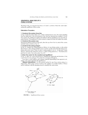
The body in Fig. 1a is acted on by forces A, B, and C, as shown. Draw the vector repre-
senting the equilibrant of this system.
Calculation Procedure:
1. Construct the system force line
In Fig. 1b, draw the vector chain A-B-C, which is termed the force line. The vector extending
from the initial point to the terminal point of the force line represents the resultant R. In any
force system, the resultant R is equal to and collinear with the equilibrant E, but acts in the op-
posite direction. The equilibrant of a force system is a single force that will balance the system.
2. Construct the system rays
Selecting an arbitrary point O as the pole, draw the rays from O to the ends of the vectors
and label them as shown in Fig. 1b.
3. Construct the string polygon
In Fig. 1a, construct the string polygon as follows: At an arbitrary point a on the action
line of force A, draw strings parallel to rays ar and ab. At the point where the string ab in-
tersects the action line of force B, draw a string parallel to ray bc. At the point where
string bc intersects the action line of force C, draw a string parallel to cr. The intersection
point Q of ar and cr lies on the action line of R.
4. Draw the vector for the resultant and equilibrant
In Fig. 1a, draw the vector representing R. Establish the magnitude and direction of this
vector from the force polygon. The action line of R passes through Q.
Last, draw a vector equal to and collinear with that representing R but opposite in di-
rection. This vector represents the equilibrant E.
Related Calculations. Use this general method for any force system acting in a
single plane. With a large number of forces, the resultant of a smaller number of forces
can be combined with the remaining forces to simplify the construction.
FIGURE 1. Equilibrant of force system.