
Page 23 - Handbook of Civil Engineering Calculations, Second Edition
P. 23
1.6 STRUCTURAL STEEL ENGINEERING AND DESIGN
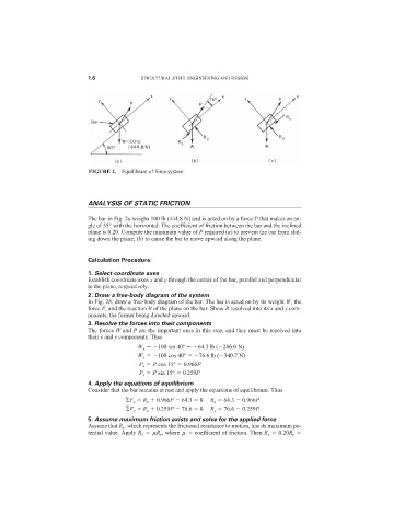
FIGURE 2. Equilibrant of force system.
ANALYSIS OF STATIC FRICTION
The bar in Fig. 2a weighs 100 lb (444.8 N) and is acted on by a force P that makes an an-
gle of 55° with the horizontal. The coefficient of friction between the bar and the inclined
plane is 0.20. Compute the minimum value of P required (a) to prevent the bar from slid-
ing down the plane; (b) to cause the bar to move upward along the plane.
Calculation Procedure:
1. Select coordinate axes
Establish coordinate axes x and y through the center of the bar, parallel and perpendicular
to the plane, respectively.
2. Draw a free-body diagram of the system
In Fig. 2b, draw a free-body diagram of the bar. The bar is acted on by its weight W, the
force P, and the reaction R of the plane on the bar. Show R resolved into its x and y com-
ponents, the former being directed upward.
3. Resolve the forces into their components
The forces W and P are the important ones in this step, and they must be resolved into
their x and y components. Thus
W x 100 sin 40° 64.3 lb ( 286.0 N)
W y 100 cos 40° 76.6 lb ( 340.7 N)
P x P cos 15° 0.966P
P y P sin 15° 0.259P
4. Apply the equations of equilibrium
Consider that the bar remains at rest and apply the equations of equilibrium. Thus
F x R x 0.966P 64.3 0 R x 64.3 0.966P
F y R y 0.259P 76.6 0 R y 76.6 0.259P
5. Assume maximum friction exists and solve for the applied force
Assume that R x , which represents the frictional resistance to motion, has its maximum po-
tential value. Apply R x R y , where coefficient of friction. Then R x 0.20R y