
Page 28 - Handbook of Civil Engineering Calculations, Second Edition
P. 28
STATICS, STRESS AND STRAIN, AND FLEXURAL ANALYSIS 1.11
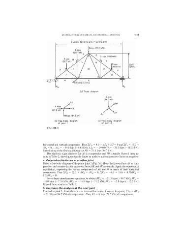
FIGURE 5
horizontal and vertical components. Thus F H 4.0 AJ H HJ 0 and F V 19.0
AJ V 0; AJ V 19.0 kips ( 84.5 kN); AJ H 19.0/0.75 25.3 kips ( 112.5 kN).
Substituting in the first equation gives HJ 21.3 kips (94.7 kN).
The algebraic signs disclose that AJ is compressive and HJ is tensile. Record these re-
sults in Table 2, showing the tensile forces as positive and compressive forces as negative.
4. Determine the forces at another joint
Draw a free-body diagram of the pin at joint 2 (Fig. 5c). Show the known force AJ as com-
pressive, and assume that the unknown forces BK and JK are tensile. Apply the equations of
equilibrium, expressing the vertical components of BK and JK in terms of their horizontal
components. Thus F H 25.3 BK H JK H 0; F V 6.0 19.0 0.75BK H
0.75JK H 0.
Solve these simultaneous equations, to obtain BK H 21.3 kips ( 94.7 kN); JK H
4.0 kips ( 17.8 kN); BK V 16.0 kips ( 71.2 kN); JK V 3.0 kips ( 13.3 kN).
Record these results in Table 2.
5. Continue the analysis at the next joint
Proceed to joint 3. Since there are no external horizontal forces at this joint, CL H BK H
21.3 kips (94.7 kN) of compression. Also, KL 6 kips (26.7 kN) of compression.