
Page 30 - Handbook of Civil Engineering Calculations, Second Edition
P. 30
STATICS, STRESS AND STRAIN, AND FLEXURAL ANALYSIS 1.13
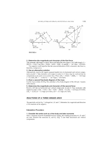
FIGURE 6
2. Determine the magnitude and character of the first force
Take moments with respect to joint 4. Since each halt of the truss forms a 3-4-5 right triangle, d
20(3/5) 12 ft (3.7 m), M 4 19(20) 6(10) 12BK 0, and BK 26.7 kips ( 118.8 kN).
The negative result signifies that the assumed direction of BK is incorrect; the force is,
therefore, compressive.
3. Use an alternative solution
Alternatively, resolve BK (again assumed tensile) into its horizontal and vertical compo-
nents at joint 1. Take moments with respect to joint 4. (A force may be resolved into its
components at any point on its action line.) Then, M 4 19(20) 20BK V 16.0 kips
( 71.2 kN); BK 16.0(5/3) 26.7 kips ( 118.8 kN).
4. Draw a second free-body diagram of the truss
Cut the truss at plane bb (Fig. 6b), and draw a free-body diagram of the left part. Assume
LM is tensile.
5. Determine the magnitude and character of the second force
Resolve LM into its horizontal and vertical components at joint 4. Take moments with
respect to joint 1: M 1 6(10 20) 3(20) 20LM V 0; LM V 12.0 kips (53.4 kN);
LM H 12.0/2.25 3.3 kips (23.6 kN); LM 13.1 kips (58.3 kN).
REACTIONS OF A THREE-HINGED ARCH
The parabolic arch in Fig. 7 is hinged at A, B, and C. Determine the magnitude and direction
of the reactions at the supports.
Calculation Procedure:
1. Consider the entire arch as a free body and take moments
Since a moment cannot be transmitted across a hinge, the bending moments at A, B, and C
are zero. Resolve the reactions R A and R C (Fig. 7) into their horizontal and vertical
components.