
Page 27 - Handbook of Civil Engineering Calculations, Second Edition
P. 27
1.10 STRUCTURAL STEEL ENGINEERING AND DESIGN
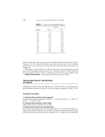
TABLE 1. Forces in Truss Members (Fig. 4)
Force
Member kips kN
AJ 6.7 29.8
BK 9.5 42.2
CN 19.8 88.0
DE 30.2 134.2
HJ 6.0 26.7
GM 13.0 57.8
FP 20.0 88.9
JK 4.5 20.0
KM 8.1 36.0
MN 8.6 38.2
NP 10.4 46.2
PE 12.6 56.0
upward to the right; NM acts upward to the left; MK and KB act downward to the left.
Therefore, CN, MK, and KB are directed away from the joint (Fig. 4); this condition
discloses that they are tensile forces. Force NM is directed toward the joint; therefore, it is
compressive.
The validity of this procedure lies in the drawing of the vectors representing external
forces while proceeding around the truss in a clockwise direction. Tensile forces are
shown with a positive sign in Table 1; compressive forces are shown with a negative sign.
Related Calculations. Use this general method for any type of truss.
TRUSS ANALYSIS BY THE METHOD
OF JOINTS
Applying the method of joints, determine the forces in the truss in Fig. 5a. The load at joint 4
has a horizontal component of 4 kips (17.8 kN) and a vertical component of 3 kips (13.3 kN).
Calculation Procedure:
1. Compute the reactions at the supports
Using the usual analysis techniques, we find R LV 19 kips (84.5 kN); R LH 4 kips (17.8
kN); R R 21 kips (93.4 kN).
2. List each truss member and its slope
Table 2 shows each truss member and its slope.
3. Determine the forces at a principal joint
Draw a free-body diagram, Fig. 5b, of the pin at joint 1. For the free-body diagram, as-
sume that the unknown internal forces AJ and HJ are tensile. Apply the equations of equi-
librium to evaluate these forces, using the subscripts H and V, respectively, to identify the