
Page 24 - Handbook of Civil Engineering Calculations, Second Edition
P. 24
STATICS, STRESS AND STRAIN, AND FLEXURAL ANALYSIS 1.7
0.20(76.6 0.259P) 15.32 0.052P. Substituting for R x from step 4 yields 64.3
0.966P 15.32 0.052P; so P 53.6 lb (238.4 N).
6. Draw a second free-body diagram
In Fig. 2c, draw a free-body diagram of the bar, with R x being directed downward.
7. Solve as in steps 1 through 5
As before, R y 76.6 0.259P. Also the absolute value of R x 0.966P 64.3. But R x
0.20R y , 15.32 0.052P. Then 0.966P 64.3 15.32 0.052P; so P 78 2 lb
(347 6N).
ANALYSIS OF A STRUCTURAL FRAME
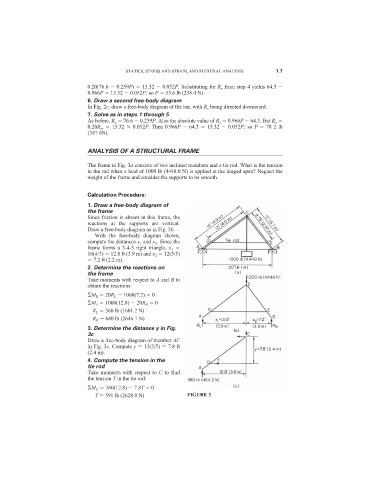
The frame in Fig. 3a consists of two inclined members and a tie rod. What is the tension
in the rod when a load of 1000 lb (4448.0 N) is applied at the hinged apex? Neglect the
weight of the frame and consider the supports to be smooth.
Calculation Procedure:
1. Draw a free-body diagram of
the frame
Since friction is absent in this frame, the
reactions at the supports are vertical.
Draw a free-body diagram as in Fig. 3b.
With the free-body diagram shown,
compute the distances x 1 and x 2 . Since the
frame forms a 3-4-5 right triangle, x 1
16(4/5) 12.8 ft (3.9 m) and x 2 12(3/5)
7.2 ft (2.2 m).
2. Determine the reactions on
the frame
Take moments with respect to A and B to
obtain the reactions:
M B 20R L 1000(7.2) 0
M A 1000(12.8) 20R R 0
R L 360 lb (1601.2 N)
R R 640 lb (2646.7 N)
3. Determine the distance y in Fig.
3c
Draw a free-body diagram of member AC
in Fig. 3c. Compute y 13(3/5) 7.8 ft
(2.4 m).
4. Compute the tension in the
tie rod
Take moments with respect to C to find
the tension T in the tie rod:
M C 360(12.8) 7.8T 0
T 591 lb (2628.8 N) FIGURE 3