Page 29 - Handbook of Civil Engineering Calculations, Second Edition
P. 29

1.12            STRUCTURAL STEEL ENGINEERING AND DESIGN

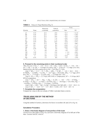
                            TABLE 2. Forces in Truss Members (Fig. 5)
                                                                                Force
                                                 Horizontal   Vertical
                            Member     Slope     component   component     kips       kN
                              AJ       0.75        25.3        19.0        31.7       141.0
                              BK       0.75        21.3        16.0        26.7       118.8
                              CL       0.75        21.3        16.0        26.7       118.8
                              DN       0.75        22.7        17.0        28.3       125.9
                              EP       0.75        22.7        17.0        28.3       125.9
                              FQ       0.75        28.0        21.0        35.0       155.7
                              HJ       0.0         21.3         0.0        21.3        94.7
                              GM       0.0         16.0         0.0        16.0        71.2
                              GQ       0.0         28.0         0.0        28.0       124.5
                              JK       0.75         4.0         3.0         5.0        22.2
                              KL                    0.0         6.0         6.0        26.7
                              LM       2.25         5.3        12.0           13.1     58.3
                              MN       2.25         6.7        15.0           16.4     72.9
                              NP                    0.0        11.0        11.0        48.9
                              PQ       0.75         5.3         4.0         6.7        29.8


                            6. Proceed to the remaining joints in their numbered order
                            Thus, for joint 4:  F H   4.0   21.3   4.0   LM H   GM   0;  F V   3.0   3.0
                            6.0   LM V   0; LM V   12.0 kips (53.4 kN); LM H   12.0/2.25   5.3 kips (23.6 kN).
                            Substituting in the first equation gives GM   16.0 kips (71.2 kN).
                              Joint 5:  F H   21.3   53   DN H   MN H   0;  F V   6.0   16.0   12.0
                            0.750DN H   2.25MN H   0; DN H   22.7 kips ( 101.0 kN); MN H   6.7 kips (29.8
                            kN); DN V   17.0 kips ( 75.6 kN); MN V   15.0 kips (66.7 kN).
                              Joint 6: EP H   DN H   22.7 kips (101.0 kN) of compression; NP   11.0 kips (48.9
                            kN) of compression.
                              Joint 7:  F H   22.7    PQ H   FQ H   0;   F V   8.0    17.0    0.75PQ H
                            0.75FQ H   0; PQ H   5.3 kips ( 23.6 kN); FQ H   28.0 kips ( 124.5 kN); PQ V
                             4.0 kips ( 17.8 kN); FQ V   21.0 kips ( 93.4 kN).
                              Joint 8:  F H   28.0   GQ   0; GQ   28.0 kips (124.5 kN);  F V   21.0   21.0   0.
                              Joint 9:  F H   16.0   6.7   5.3   28.0   0;  F V 15.0  11.0   4.0   0.
                            7. Complete the computation
                            Compute the values in the last column of Table 2 and enter them as shown.


                            TRUSS ANALYSIS BY THE METHOD
                            OF SECTIONS

                            Using the method of sections, determine the forces in members BK and LM in Fig. 6a.

                            Calculation Procedure:
                            1. Draw a free-body diagram of one portion of the truss
                            Cut the truss at the plane aa (Fig. 6a), and draw a free-body diagram of the left part of the
                            truss. Assume that BK is tensile.
   24   25   26   27   28   29   30   31   32   33   34