
Page 39 - Handbook of Civil Engineering Calculations, Second Edition
P. 39
1.22 STRUCTURAL STEEL ENGINEERING AND DESIGN
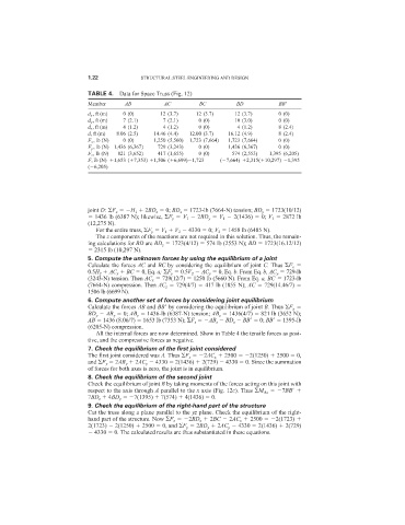
TABLE 4. Data for Space Truss (Fig. 12)
Member AB AC BC BD BB
d x , ft (m) 0 (0) 12 (3.7) 12 (3.7) 12 (3.7) 0 (0)
d y , ft (m) 7 (2.1) 7 (2.1) 0 (0) 10 (3.0) 0 (0)
d z , ft (m) 4 (1.2) 4 (1.2) 0 (0) 4 (1.2) 8 (2.4)
d, ft (m) 8.06 (2.5) 14.46 (4.4) 12.00 (3.7) 16.12 (4.9) 8 (2.4)
F x , lb (N) 0 (0) 1,250 (5,560) 1,723 (7,664) 1,723 (7,664) 0 (0)
F y , lb (N) 1,436 (6,367) 729 (3,243) 0 (0) 1,436 (6,367) 0 (0)
F z , lb (N) 821 (3,652) 417 (1,655) 0 (0) 574 (2,553) 1,395 (6,205)
F, lb (N) 1,653 ( 7,353) 1,506 ( 6,699) 1,723 ( 7,664) 2,315( 10,297) 1,395
( 6,205)
joint D: F x H 1 2BD x 0; BD x 1723-lb (7664-N) tension; BD y 1723(10/12)
1436 lb (6387 N); likewise, F y V 1 2BD y V 1 2(1436) 0; V 1 2872 lb
(12,275 N).
For the entire truss, F y V 1 V 2 4330 0; V 2 1458 lb (6485 N).
The z components of the reactions are not required in this solution. Thus, the remain-
ing calculations for BD are BD z 1723(4/12) 574 lb (2553 N); BD 1723(16.12/12)
2315 lb (10,297 N).
5. Compute the unknown forces by using the equilibrium of a joint
Calculate the forces AC and BC by considering the equilibrium of joint C. Thus F x
0.5H 2 AC x BC 0, Eq. a; F y 0.5V 2 AC y 0, Eq. b. From Eq. b, AC y 729-lb
(3243-N) tension. Then AC x 729(12/7) 1250 lb (5660 N). From Eq. a, BC 1723-lb
(7664-N) compression. Then AC z 729(4/7) 417 lb (1855 N); AC 729(14.46/7)
1506 lb (6699 N).
6. Compute another set of forces by considering joint equilibrium
Calculate the forces AB and BB
by considering the equilibrium of joint B. Thus F y
BD y AB y 0; AB y 1436-lb (6387-N) tension; AB z 1436(4/7) 821 lb (3652 N);
AB 1436 (8.06/7) 1653 lb (7353 N); F z AB z BD z BB
0; BB
1395-lb
(6205-N) compression.
All the internal forces are now determined. Show in Table 4 the tensile forces as posi-
tive, and the compressive forces as negative.
7. Check the equilibrium of the first joint considered
The first joint considered was A. Thus F x 2AC x 2500 2(1250) 2500 0,
and F y 2AB y 2AC y 4330 2(1436) 2(729) 4330 0. Since the summation
of forces for both axes is zero, the joint is in equilibrium.
8. Check the equilibrium of the second joint
Check the equilibrium of joint B by taking moments of the forces acting on this joint with
respect to the axis through A parallel to the x axis (Fig. 12c). Thus M Ax 7BB
7BD z 4BD y 7(1395) 7(574) 4(1436) 0.
9. Check the equilibrium of the right-hand part of the structure
Cut the truss along a plane parallel to the yz plane. Check the equilibrium of the right-
hand part of the structure. Now F x 2BD x 2BC 2AC x 2500 2(1723)
2(1723) 2(1250) 2500 0, and F y 2BD y 2AC y 4330 2(1436) 2(729)
4330 0. The calculated results are thus substantiated in these equations.