
Page 36 - Handbook of Civil Engineering Calculations, Second Edition
P. 36
STATICS, STRESS AND STRAIN, AND FLEXURAL ANALYSIS 1.19
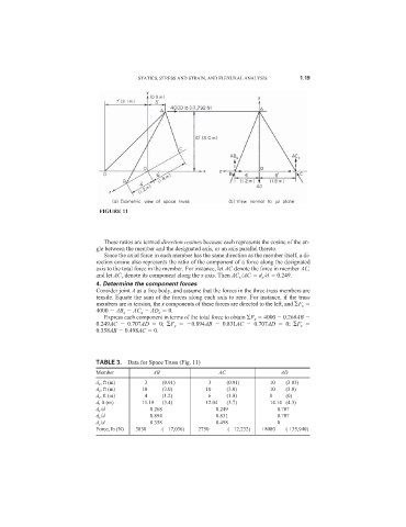
FIGURE 11
These ratios are termed direction cosines because each represents the cosine of the an-
gle between the member and the designated axis, or an axis parallel thereto.
Since the axial force in each member has the same direction as the member itself, a di-
rection cosine also represents the ratio of the component of a force along the designated
axis to the total force in the member. For instance, let AC denote the force in member AC,
and let AC x denote its component along the x axis. Then AC x /AC d x /d 0.249.
4. Determine the component forces
Consider joint A as a free body, and assume that the forces in the three truss members are
tensile. Equate the sum of the forces along each axis to zero. For instance, if the truss
members are in tension, the x components of these forces are directed to the left, and F x
4000 AB x AC x AD x 0.
Express each component in terms of the total force to obtain F x 4000 0.268AB
0.249AC 0.707AD 0; F y 0.894AB 0.831AC 0.707AD 0; F z
0.358AB 0.498AC 0.
TABLE 3. Data for Space Truss (Fig. 11)
Member AB AC AD
d x , ft (m) 3 (0.91) 3 (0.91) 10 (3.03)
d y , ft (m) 10 (3.0) 10 (3.0) 10 (3.0)
d z , ft (m) 4 (1.2) 6 (1.8) 0 (0)
d, ft (m) 11.18 (3.4) 12.04 (3.7) 14.14 (4.3)
d x /d 0.268 0.249 0.707
d y /d 0.894 0.831 0.707
d z /d 0.358 0.498 0
Force, lb (N) 3830 ( 17,036) 2750 ( 12,232) 8080 ( 35,940)