
Page 89 - Handbook of Civil Engineering Calculations, Second Edition
P. 89
1.72 STRUCTURAL STEEL ENGINEERING AND DESIGN
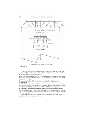
FIGURE 49
To locate the resultant of the load system, take moments with respect to load 1. Thus, R
50 kips (222.4 kN). Then M 1 12(6) 18(16) 15(22) 50x; x 13.8 ft (4.21 m).
2. Construct the influence line for V de
In Fig. 49c, draw the influence line for V de . Assume right-to-left locomotion, and express
the slope of each segment of the influence line. Thus slope of ik slope of ma 1/200;
slope of km 7/200.
3. Assume a load position, and determine whether V de increases
or decreases
Consider that load 1 lies within panel de and the remaining loads lie to the right of this panel.
From the slope of the influence line, ascertain whether V de increases or decreases as the system
is displaced to the left. Thus dV de /dx 5( 7/200) 45(1/200) > 0; V de increases.
4. Repeat the foregoing calculation with other assumed load positions
Consider that loads 1 and 2 lie within the panel de and the remaining loads lie to the right
of this panel. Repeat the foregoing calculation. Thus dV de /dx 17( 7/200) 33(1/200)
< 0; V de decreases.
From these results it is concluded that as the system moves from right to left, V de is
maximum at the instant that load 2 is at e.