
Page 91 - Handbook of Civil Engineering Calculations, Second Edition
P. 91
1.74 STRUCTURAL STEEL ENGINEERING AND DESIGN
Calculation Procedure:
1. Place the unit load in position, and compute the
bending moment
The moment of all forces acting on the truss at panel points to the left of b with respect to
b is termed the bending moment at that point. Assume that the load transmitted to the giv-
en truss is 1 kip (4.45 kN), and let x denote the instantaneous distance from the right-hand
support to the moving load.
Place the unit load to the right of C, and compute the bending moment M b . Thus R L
x/120; M b 45R L 3x/8, Eq. a.
2. Place the unit load on the other side and compute the
bending moment
Placing the unit load to the left of B and computing M b , M b 45R L (x 75) 5x/8
75, Eq. b.
3. Place the unit load within the panel; compute the panel-point
load and bending moment
Place the unit load within panel BC. Determine the panel-point load P B and compute M b .
Thus P B (x 60)/30 x/30 2; M b 45R L 15P B 3x/8 15(x/30 2) x/8
30, Eq. c.
4. Applying the foregoing equations, draw the influence line
Figure 50b shows the influence line for M b . Computing the significant values yields CG
(3/8)(60) 22.50 ft·kips (30.51 kN·m); BH (5/8)(90) 75 18.75 ft·kips
(25.425 kN·m).
5. Compute the slope of each segment of the influence line
This computation is made for subsequent reference. Thus, line a, dM b /dx 3/8; line b,
dM b /dx 5/8; line c, dM b /dx 1/8.
FORCE IN TRUSS CHORD CAUSED BY
MOVING CONCENTRATED LOADS
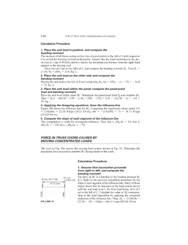
The truss in Fig. 50a carries the moving-load system shown in Fig. 51. Determine the
maximum force induced in member BC during transit of the loads.
Calculation Procedure:
1. Assume that locomotion proceeds
from right to left, and compute the
bending moment
The force in BC is a function of the bending moment M b
at b. Refer to the previous calculation procedure for the
slope of each segment of the influence line. Study of these
slopes shows that M b increases as the load system moves
until the rear load is at C, the front load being 14 ft (4.3
m) to the left of C. Calculate the value of M b correspon-
ding to this load disposition by applying the computed
properties of the influence line. Thus, M b 22.50(24)
FIGURE 51 (22.50 1/8 14)(6) 664.5 ft·kips (901.06 kN·m).