
Page 94 - Handbook of Civil Engineering Calculations, Second Edition
P. 94
STATICS, STRESS AND STRAIN, AND FLEXURAL ANALYSIS 1.77
DEFLECTION OF A BEAM UNDER
MOVING LOADS
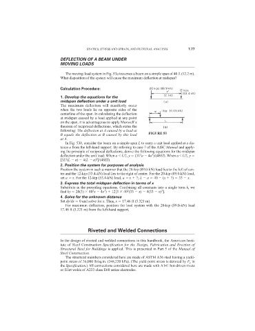
The moving-load system in Fig. 53a traverses a beam on a simple span of 40 ft (12.2 m).
What disposition of the system will cause the maximum deflection at midspan?
Calculation Procedure:
1. Develop the equations for the
midspan deflection under a unit load
The maximum deflection will manifestly occur
when the two loads lie on opposite sides of the
centerline of the span. In calculating the deflection
at midspan caused by a load applied at any point
on the span, it is advantageous to apply Maxwell’s
theorem of reciprocal deflections, which states the
following: The deflection at A caused by a load at
B equals the deflection at B caused by this load FIGURE 53
at A.
In Fig. 53b, consider the beam on a simple span L to carry a unit load applied at a dis-
tance a from the left-hand support. By referring to case 7 of the AISC Manual and apply-
ing the principle of reciprocal deflections, derive the following equations for the midspan
3
2
deflection under the unit load: When a < L/2, y (3L a 4a )/(48EI). When a < L/2, y
3
2
[3L (L a) 4(L a) ]/(48EI).
2. Position the system for purposes of analysis
Position the system in such a manner that the 20-kip (89.0-kN) load lies to the left of cen-
ter and the 12-kip (53.4-kN) load lies to the right of center. For the 20-kip (89.0-kN) load,
set a x. For the 12-kip (53.4-kN) load, a x 7; L a 40 (x 7) 33 x.
3. Express the total midspan deflection in terms of x
Substitute in the preceding equations. Combining all constants into a single term k, we
2
3
3
2
find ky 20(3) 40 x 4x ) 12[3 40 (33 x) 4(33 x) ].
4. Solve for the unknown distance
Set dy/dx 0 and solve for x. Thus, x 17.46 ft (5.321 m).
For maximum deflection, position the load system with the 20-kip (89.0-kN) load
17.46 ft (5.321 m) from the left-hand support.
Riveted and Welded Connections
In the design of riveted and welded connections in this handbook, the American Insti-
tute of Steel Construction Specification for the Design, Fabrication and Erection of
Structural Steel for Buildings is applied. This is presented in Part 5 of the Manual of
Steel Construction.
The structural members considered here are made of ASTM A36 steel having a yield-
point stress of 36,000 lb/sq.in. (248,220 kPa). (The yield-point stress is denoted by F y in
the Specification.) All connections considered here are made with A141 hot-driven rivets
or fillet welds of A233 class E60 series electrodes.